Electronic equipment and wireless communication method

A technology of electronic equipment and remote equipment, applied in wireless communication, electrical components, etc., can solve problems such as low reliability and long delay, and achieve the effect of improving reliability, reducing delay, and meeting QoS requirements

Inactive Publication Date: 2018-10-09
SONY CORP
View PDF0 Cites 6 Cited by
  • Summary
  • Abstract
  • Description
  • Claims
  • Application Information

AI Technical Summary

Problems solved by technology

[0003] In the above-mentioned network architecture, when the remote user needs to perform services such as VoIP (Voice over Internet Protocol, Internet phone), streaming media service (Streaming Services), the remote user needs to request the network side device before each service frequency resources, resulting in a large delay and low reliability

Method used


Image

  • Electronic equipment and wireless communication method
  • Electronic equipment and wireless communication method
  • Electronic equipment and wireless communication method

Examples


no. 2 example

[0043] 4. The third embodiment

no. 6 example

[0047] 8. Application examples.

[0048]

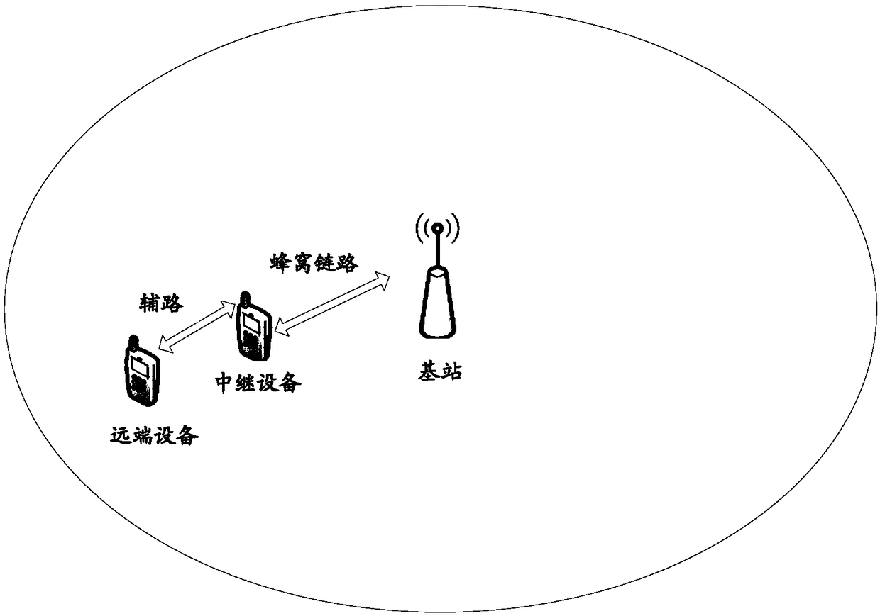
[0049] FIG. 1( a ) is a schematic diagram illustrating an application scenario of the present disclosure. As shown in Figure 1(a), there are relay devices and remote devices within the coverage of the base station, and the remote devices communicate with the base station that provides services for the relay device through the relay device. Specifically, the remote device communicates with the relay device through a sidelink, and the relay device communicates with the base station through a cellular link.

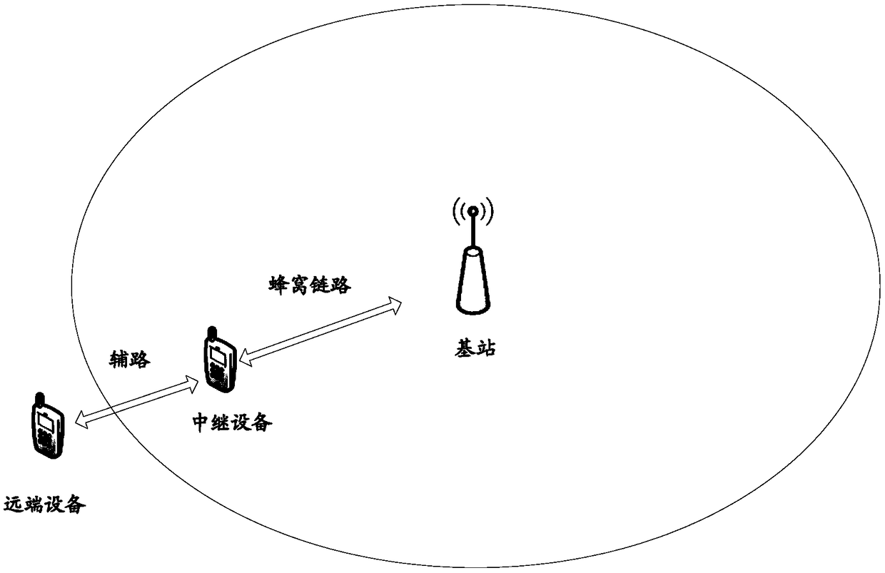
[0050] Fig. 1(b) is a schematic diagram illustrating another application scenario of the present disclosure. As shown in Figure 1(b), there is a relay device within the coverage of the base station, while the remote device is located outside the coverage of the base station. The remote device communicates with the base station providing services for the relay device through the relay device. Specifically, the remote device commun...

no. 3 example

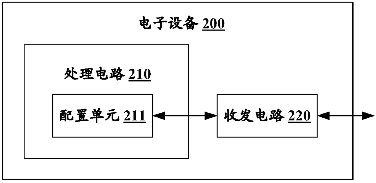
[0137] In this embodiment, an electronic device 900 according to an embodiment of the present disclosure will be described in detail. The electronic device 900 here may be a remote device in a wireless communication system, such as the remote device shown in FIG. 1( a ) and FIG. 1( b ). Figure 9 is a block diagram showing an example of the configuration of the electronic device 900 according to the embodiment of the present disclosure.

[0138] Such as Figure 9 As shown, the electronic device 900 may include a processing circuit 910 and a transceiver circuit 920 . It should be noted that the electronic device 900 may include one processing circuit 910 or may include multiple processing circuits 910 .

[0139] Further, the processing circuit 910 may include various discrete functional units to perform various functions and / or operations. It should be noted that these functional units may be physical entities or logical entities, and units with different titles may be reali...


PUM


Abstract

The invention relates to electronic equipment and a wireless communication method. The electronic equipment of the invention comprises a processing circuit and a transmitting and receiving circuit, wherein the processing circuit is configured to perform semi-persistent scheduling (SPS) configuration on remote equipment, and the remote equipment communicates with the electronic equipment via relayequipment within a service range of the electronic equipment; and the transmitting and receiving equipment is configured to transmit SPS configuration information of the remote equipment to the relayequipment. According to the electronic equipment and wireless communication method of the invention, the SPS technology can be applied to communication between equipment so as to meet service qualityrequirements of different services and traffic types.

Description

technical field [0001] Embodiments of the present disclosure generally relate to the field of wireless communication, and specifically relate to electronic equipment and a wireless communication method. More specifically, the present disclosure relates to an electronic device serving as a network-side device, an electronic device serving as a relay device, an electronic device serving as a remote device, a wireless communication method performed by a network-side device, a A wireless communication method performed by a relay device and a wireless communication method performed by a remote device. Background technique [0002] In the FeD2D (Further enhanced Device to Device, further enhanced device to device) communication system, a remote user (remote UE) can communicate with a network side device (such as a base station, including but not limited to eNB (eNB) through a relay user (relay UE) type node B)) to communicate. Specifically, the remote user communicates with the ...

Claims


Application Information

Patent Timeline
Patent Type & Authority Applications(China)
IPC IPC(8): H04W72/04H04W88/04
CPCH04W72/0453H04W88/04H04W72/20H04W72/23H04W92/10H04W92/18
Inventor 张文博孙晨
Owner SONY CORP
Why Eureka
Try Eureka