Eureka AIR delivers breakthrough ideas for toughest innovation challenges, trusted by R&D personnel around the world.

Method and wireless relay system for realizing service flow transmission of mobile terminal

A mobile terminal, service flow technology, applied in transmission systems, radio transmission systems, wireless communications, etc.

Active Publication Date: 2010-12-29
ZTE CORP
View PDF3 Cites 19 Cited by
  • Summary
  • Abstract
  • Description
  • Claims
  • Application Information

AI Technical Summary

Problems solved by technology

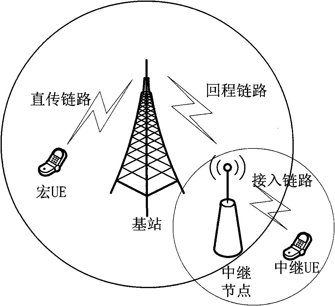
Then the problem that needs to be solved is how to meet the QoS requirements of each service of the UE under the Relay when the Relay is used as the scheduled entity on the Un interface

Method used


Image

  • Method and wireless relay system for realizing service flow transmission of mobile terminal
  • Method and wireless relay system for realizing service flow transmission of mobile terminal
  • Method and wireless relay system for realizing service flow transmission of mobile terminal

Examples


Embodiment 1

[0058] The donor base station allocates a logical channel for each service data flow of each mobile terminal under the relay station, and corresponds the data flow of different services of the mobile terminal to the logical channel one by one, and the identification of the logical channel is determined by the identification of the mobile terminal and the service Identity synthesis (that is, UE ID+UE service ID). The UE ID can be an internal ID used on a Un port. Different UEs under the relay station have different IDs. For example, it can be the Cell Radio Network Temporary Identifier (C-RNTI for short) of the UE under the relay station, and the UE service ID Represents different services under a UE, such as EPS ID or E-RAB ID.

[0059] In the prior art, the maximum number of logical channels corresponding to each UE on the Uu interface of the base station is 16. In the present invention, through the above-mentioned identification method, each logical channel corresponds to a ...

Embodiment 2

[0072] Such as Figure 15 As shown, the donor base station maps one or more different service data flows within the same service quality range to the same logical channel at the PDCP module, that is, performs priority scheduling on the service data flows of each UE. Scheduling is responsible for completing the priority among different services of different UEs, but does not involve the allocation of the services in all physical resources.

[0073] The quality of service range is determined by the donor base station, and can be formulated according to various parameter values ​​in the QoS parameters. For example, it can be the same QoS, or the same QCI in QoS and other rules to map multiple service data flows to the same logical channel, so that subsequent MAC The number of logical channels on the layer is less than that in the first embodiment, so as to reduce the processing amount of logical channel data scheduling performed by the subsequent MAC layer scheduling priority pro...


PUM


Abstract

The invention provides a method and a wireless relay system for realizing the service flow transmission of a mobile terminal. The system comprises a control base station and a relay station which are connected with each other through a backhaul link, wherein the control station is used for setting a logic channel for the service data stream of the mobile terminal under the relay station and transmitting each service data stream of each mobile terminal on the set logic channel; and the relay station is used for transmitting each service data stream of each mobile terminal on the logic channel set by the control base station. In the system, into which the relay is introduced, when the relay is used as a dispatched body, the QoS requirements of each service of user equipment (EU) under the relay are met.

Description

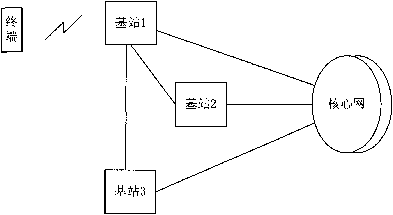
technical field [0001] The invention relates to a cellular wireless communication system, in particular to a method for realizing terminal service flow transmission and a wireless relay system. Background technique [0002] Such as figure 1 As shown, the cellular wireless communication system is mainly composed of a core network (Core Network, CN for short), an access network (Radio Access Network, RAN for short) and terminals. The core network is responsible for non-access stratum affairs, such as terminal location update, and is the anchor point of the user plane. The access network includes base stations, or base stations and base station control. The access network is responsible for access layer affairs (such as the management of wireless resources). There may be physical or logical connections between base stations according to actual conditions, such as figure 1 The connection between base station 1 and base station 2 or base station 3, and each base station can be ...

Claims


Application Information

Patent Timeline
Patent Type & Authority Applications(China)
IPC IPC(8): H04W28/06H04W28/24H04W72/12H04W88/04H04W4/00
CPCH04W84/047H04B7/2606H04W88/08H04W4/00H04W80/02H04B7/15528
Inventor 黄亚达李大鹏
Owner ZTE CORP
Why Eureka
Eureka Blog
Learn More