Tubular pile mould closing mechanism

A mold clamping mechanism and pipe pile technology, applied in the direction of the mold, can solve the problems of inconsistent tightening degree of bolts, unrealistic time-consuming, and quality decline of pipe piles, etc.

Pending Publication Date: 2018-10-12
苏州睿立汇自动化科技有限公司
View PDF0 Cites 12 Cited by
  • Summary
  • Abstract
  • Description
  • Claims
  • Application Information

AI Technical Summary

Problems solved by technology

[0002] The pipe pile mold needs to be closed up and down for the next step. The upper and lower molds are fixed by bolts. Since the pipe pile mold is relatively long and there are many bolts, manual locking is not practical and takes a long time. The tightening degree is not consistent, resulting in a decline in the quality of the pipe pile; the exis

Method used


Image

  • Tubular pile mould closing mechanism
  • Tubular pile mould closing mechanism
  • Tubular pile mould closing mechanism

Examples


Embodiment

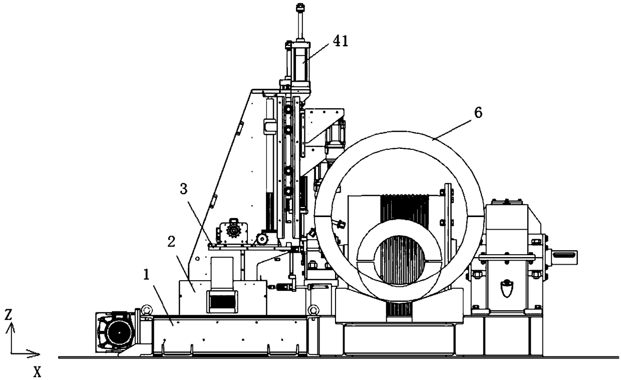
[0022] refer to Figure 1-4 As shown, this embodiment is a pipe pile mold clamping mechanism, including several linear modules, wind gun assemblies and flip assemblies located on the linear modules;

[0023] Several linear modules include a first linear module moving along the X-axis direction, a second linear module moving along the Y-axis direction, and a third linear module moving along the Z-axis direction;

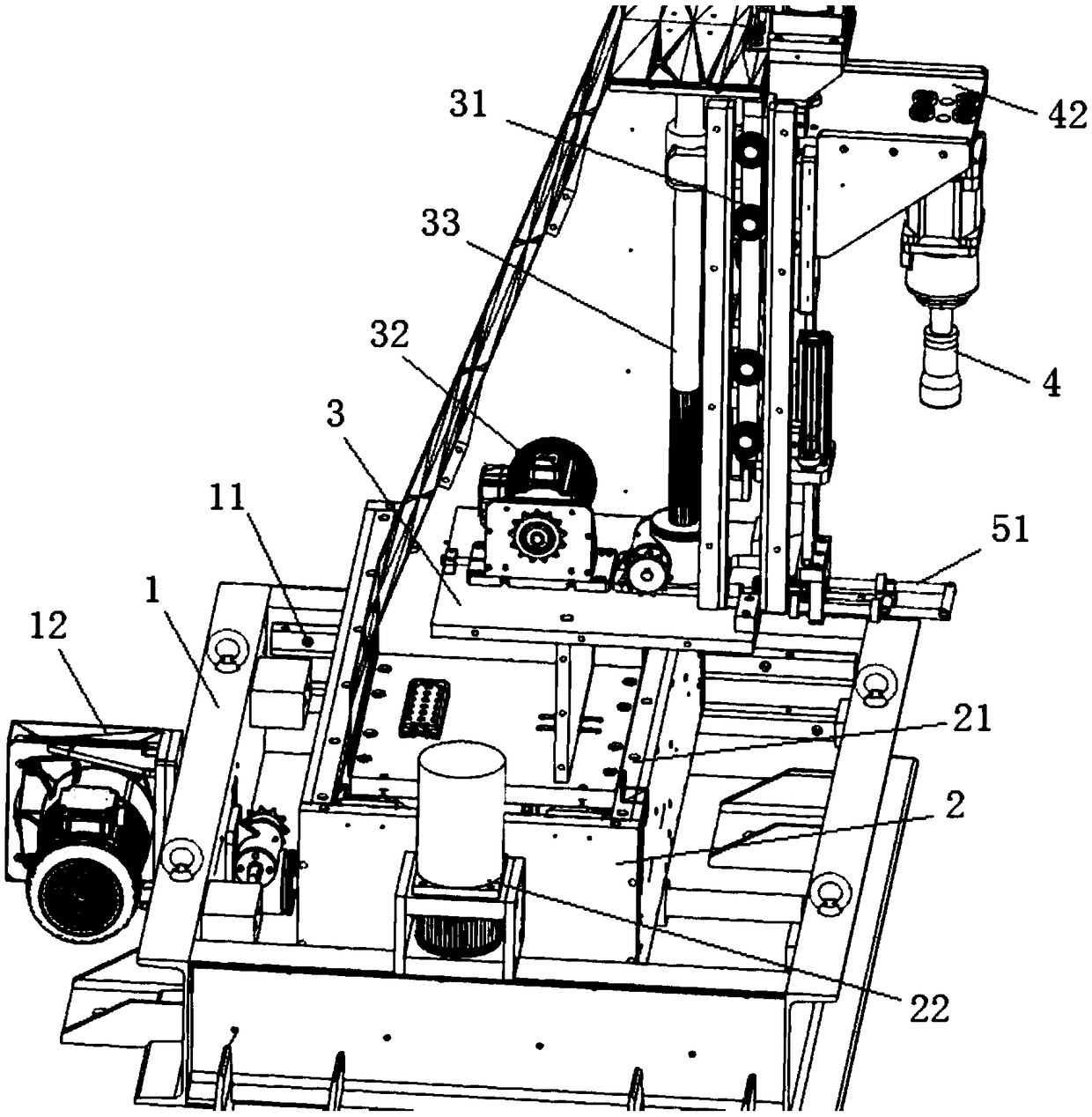
[0024] The first linear module includes a first baffle plate 1 surrounding it, a first slide rail 11 arranged in the first baffle plate 1, and a first drive motor 12 connected to the first slide rail 11;

[0025] The second linear module includes the second baffle plate 2 that is surrounded around, the second slide rail 21 that is located in the second baffle plate 2, the second drive motor 22 that connects the second slide rail 21; the second baffle plate 2 The bottom is erected in the first slide rail 11;

[0026] The third linear module includes a support plate 3...


PUM


Abstract

The invention discloses a tubular pile mould closing mechanism. The mechanism comprises a plurality of linear modules, and a jackhammer assembly and an overturning assembly which are arranged on the linear modules. The jackhammer assembly comprises a jackhammer moving up and down. The overturning assembly comprises an overturning frame moving front, back, up and down. The position of the overturning frame corresponds to that of the jackhammer. A to-be-locked tubular pile mould is arranged between the overturning frame and the jackhammer and comprises an upper half tube and a lower half tube. An upper edge is arranged on the lateral side of the upper half tube, and a lower edge is arranged on the lateral side of the lower half tube. The upper edge and the lower edge are matched in a corresponding mode and enable mould closing to be achieved. A plurality of corresponding grooves aligned with each other are formed in the upper edge and the lower edge correspondingly. Clamping components penetrating through the tails of bolts are formed in the grooves of the lower edge. The bolts are hung upside down in the grooves. The overturning frame enables the bolts to be overturned by 180 degrees, so that the heads of the bolts correspond to the jackhammer. According to the tubular pile mould closing mechanism, the tubular pile mould closing direction adjustment is fast, and the bolts are locked in place.

Description

technical field [0001] The invention belongs to the technical field of pipe pile production, and in particular relates to a pipe pile mold clamping mechanism. Background technique [0002] The pipe pile mold needs to be closed up and down for the next step. The upper and lower molds are fixed by bolts. Since the pipe pile mold is relatively long and there are many bolts, manual locking is not practical and takes a long time. The tightening degree is not consistent, resulting in a decline in the quality of the pipe pile; the existing pipe pile mold clamping mechanism uses the mold clamping transport rail to transport the pipe pile mold to the corresponding screw locking machine fixing position, which cannot follow the waiting time of the pipe pile due to the position limitation of the screw locking machine. The locking position can be adjusted in multiple angles or directions. Contents of the invention [0003] The object of the present invention is to solve the above-ment...

Claims


Application Information

Patent Timeline
IPC IPC(8): B28B21/76
CPCB28B21/76
Inventor 徐乐
Owner 苏州睿立汇自动化科技有限公司
Why Eureka
Try Eureka