Multi-angle automatic steel structure placing equipment

A multi-angle, steel structure technology, applied in the direction of load hanging components, transportation and packaging, etc., can solve the problems of I-beam hoisting such as falling, manual work, and inability to pick up I-beam, so as to increase the transmission accuracy Effect

Active Publication Date: 2018-10-12
正一集团有限公司
View PDF6 Cites 11 Cited by
  • Summary
  • Abstract
  • Description
  • Claims
  • Application Information

AI Technical Summary

Problems solved by technology

[0004] In order to solve the above problems, the present invention provides a multi-angle automatic placement equipment for steel structures, which can solve the problems that the existing I-beams cannot be stably clamped and the I-beams are hoisted and transported. The hidden danger of falling, the angle of the I-beam cannot be adjusted when it is transferred to the installation position, the I-beam cannot be fixed in all directions when the I-beam is transferred, there is a safety hazard in the transfer of the I-beam, and the I-beam is transferred to the installation position It is necessary to manually adjust its position and other problems; it can realize the stable lifting and placement of the I-beam, the all-round fixing of the I-beam, and the function of transporting the I-beam to a suitable position. Stable clamping, no hidden danger of I-beam hoisting, I-beam angle can be adjusted when I-beam is transferred to the installation position, I-beam can be fixed in all directions when I-beam is transferred, I-beam There is no safety hazard in steel transmission, and the position of I-beam is automatically adjusted when it is transported to the installation position.

Method used


Image

  • Multi-angle automatic steel structure placing equipment
  • Multi-angle automatic steel structure placing equipment
  • Multi-angle automatic steel structure placing equipment

Examples


Embodiment Construction

[0028] In order to make the technical means, creative features, goals and effects achieved by the present invention easy to understand, the present invention will be further described below in conjunction with specific illustrations. It should be noted that, in the case of no conflict, the embodiments in the present application and the features in the embodiments can be combined with each other.

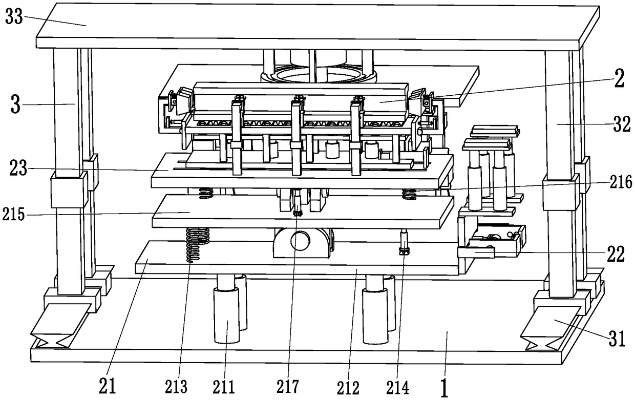
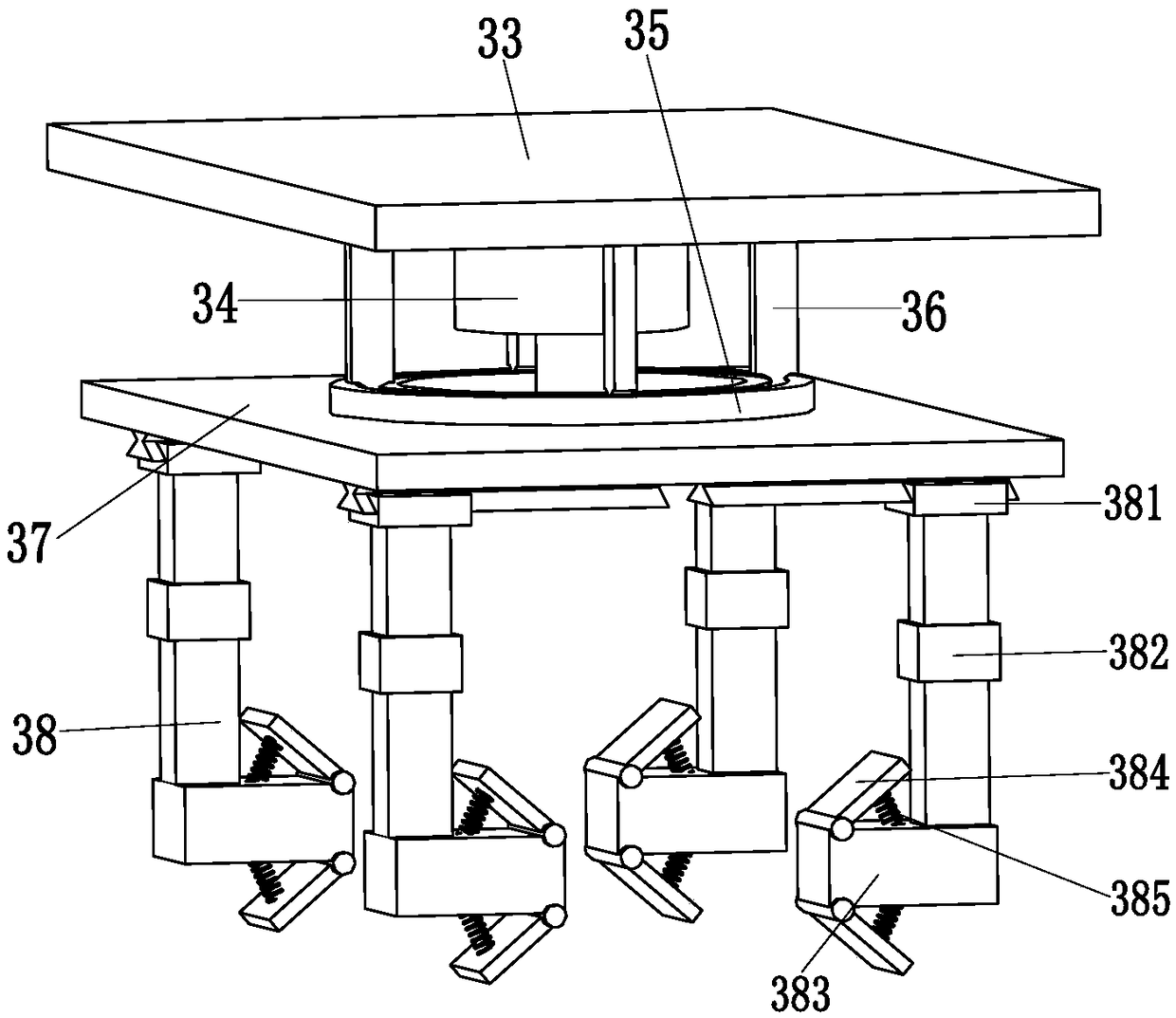
[0029] Such as Figure 1 to Figure 6 As shown, a steel structure multi-angle automatic placement equipment includes a support base plate 1, a lifting device 2 and a grabbing device 3. The lifting device 2 is installed on the front end of the support base plate 1, and the grabbing device 3 is installed on the support On the top of the rear end of the bottom plate 1.

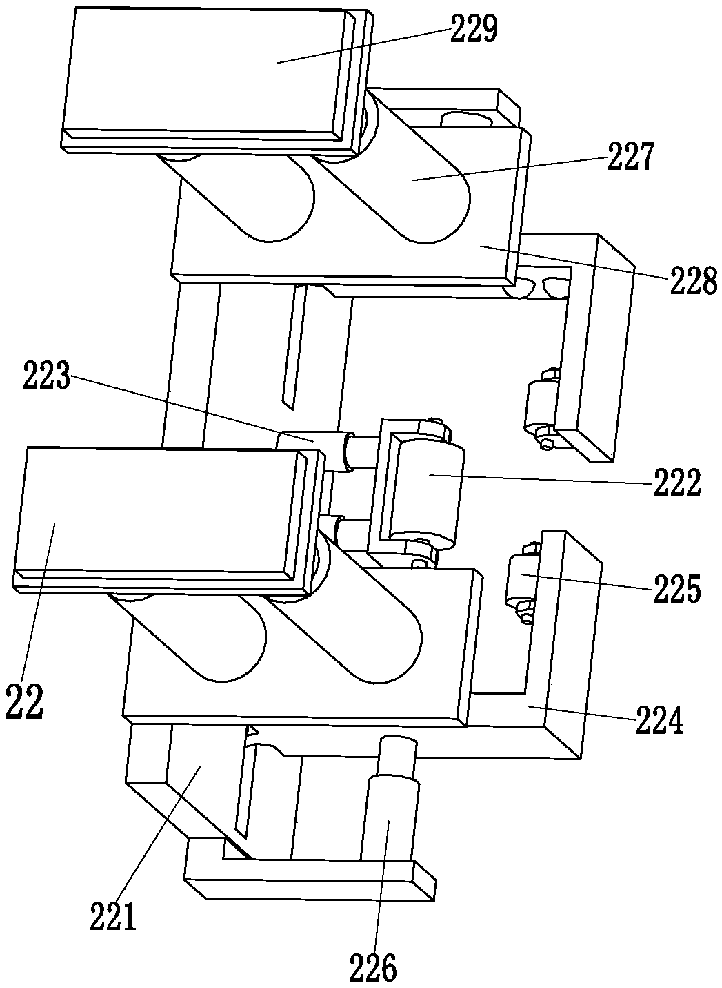
[0030] The lifting device 2 includes a lifting adjustment mechanism 21, a limit mechanism 22, a fixed base plate 23, a locking mechanism 24, a side fixed branch chain 25 and a locking mechanism 26, and the lifting adjus...


PUM


Abstract

The invention relates to multi-angle automatic steel structure placing equipment. The equipment comprises a supporting bottom plate, a lifting device and a grabbing device. The lifting device is installed on the top of the front end of the supporting bottom plate. The grabbing device is installed on the top of the rear end of the supporting bottom plate. The lifting device comprises a lifting adjusting mechanism, a limiting mechanism, a fixing bottom plate, a locking mechanism, a side fixing branch chain and a clamping mechanism. The grabbing device comprises a grabbing electric sliding block,a grabbing telescoping column, a grabbing top plate, a grabbing motor, a grabbing sliding groove, a grabbing sliding rod, a grabbing supporting plate and a grabbing mechanism. The equipment can solvethe problems that when existing H-shaped steel is hoisted and conveyed, the H-shaped steel cannot be clamped stably, the hidden danger of falling of the H-shaped steel in the hoisting process exists,when the H-shaped steel is conveyed to the installing position, the angle cannot be adjusted, when the H-shaped steel is conveyed, the H-shaped steel cannot be fixed in an all-directional manner, andwhen the H-shaped steel is conveyed to the installing position, the position needs to be adjusted manually.

Description

technical field [0001] The invention relates to the technical field of building steel structures, in particular to a multi-angle automatic placement device for steel structures. Background technique [0002] Steel structure is a structure composed of steel materials, which is one of the main types of building structures. The structure is mainly composed of steel beams, steel columns, steel trusses and other components made of section steel and steel plates. It is simple and widely used in large-scale workshops, venues, super high-rises and other fields; steel structure pillars and cross columns need to be built first during steel structure construction. I-beams are erected and installed on the column. Because different designs require I-beams to be installed with a certain inclination angle, or I-beams need to be installed in staggered positions, this will bring many difficulties to the transmission of I-beams. [0003] The transmission of I-beams is generally completed by ...

Claims


Application Information

Patent Timeline
Patent Type & Authority Applications(China)
IPC IPC(8): B66C1/42B66C1/44
CPCB66C1/42B66C1/442
Inventor 莫小雨
Owner 正一集团有限公司
Why Eureka
Try Eureka