Supercharge Your Innovation With Domain-Expert AI Agents!

Structural column construction device and method

A technology of construction equipment and construction methods, which is applied in building construction, on-site preparation of building components, formwork/formwork/working frame, etc., which can solve the problems of low construction efficiency, defects in structural columns, and impacts on the load-bearing and support of structural columns effect and other issues, to achieve the effect of scientific construction method, novel structure and strong practicability

Active Publication Date: 2018-10-12
FUJIAN HUIDONG CONSTR ENG CO LTD
View PDF6 Cites 0 Cited by
  • Summary
  • Abstract
  • Description
  • Claims
  • Application Information

AI Technical Summary

Problems solved by technology

[0002] When the wall is built inside the main frame of the building, when the length of the wall exceeds 5 meters, it is necessary to pour structural columns in the middle of the wall to support it. When the wall is built, a space will be reserved at the target position. After binding the steel frame in the horse-tooth tree, first stick foam strips on the edge of the horse-tooth tree, and then lay the pouring formwork on the front and rear sides of the horse-tooth tree. At present, the laying of the pouring formwork mainly adopts front and rear A long strip of wood is used as the formwork, and the front and rear two formworks are fastened by multiple tensioned steel bars and wooden corrugations to form the pouring formwork. The area between the front and rear two pouring formworks is used as the pouring space, and finally A pouring opening is cut at the top of the formwork on the front side, and the concrete is poured into the pouring space one by one through a wooden hopper. This construction method has the following problems. First, the construction efficiency is low; second, the concrete poured into the pouring space It cannot be fully mixed, resulting in the inability of the concrete to be fully integrated with the steel frame, resulting in flaws in the structural columns after shaping, which will also affect the load-bearing and supporting effects of the structural columns

Method used


Image

  • Structural column construction device and method
  • Structural column construction device and method
  • Structural column construction device and method

Examples


Embodiment Construction

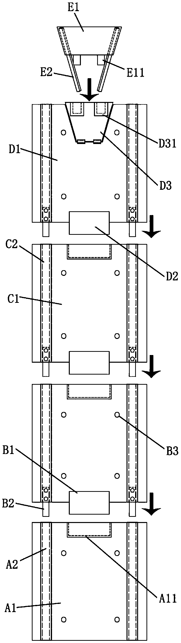
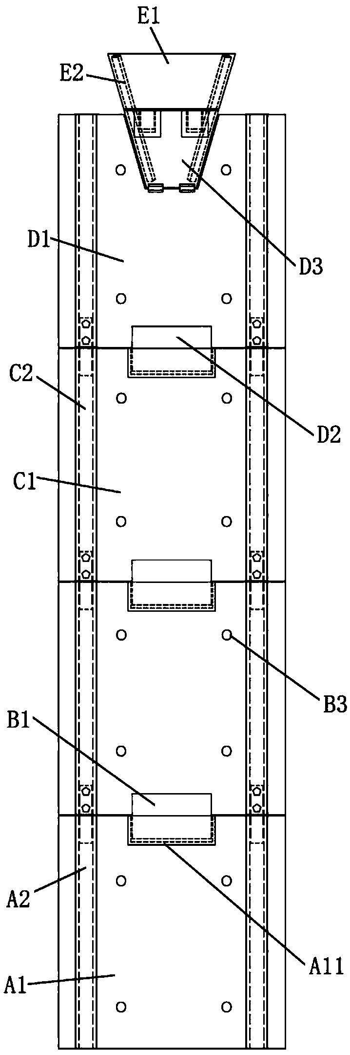
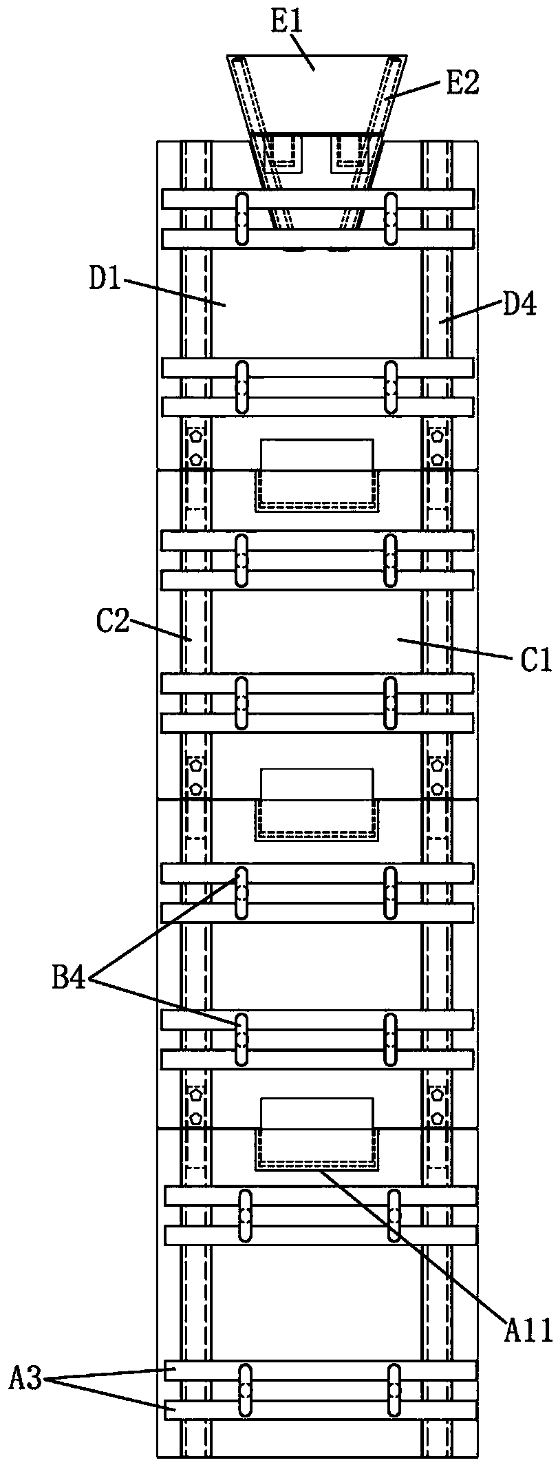
[0048] like figure 1 , figure 2 , image 3 As shown, a construction column construction equipment is composed of a bottom formwork body, 2 middle formwork bodies, a top formwork body, and a feed guide bucket, and is characterized in that,

[0049] The bottom formwork body is located at the lowermost end, the top of the bottom formwork body is connected with a first intermediate formwork body, the top of the first intermediate formwork body is connected with a second intermediate formwork body, and the top of the second intermediate formwork body The top is connected with the top mold frame body, and the feeding guide bucket can be buckled downward to the front upper end of the top mold frame body;

[0050] The bottom formwork body, the first middle formwork body, the second middle formwork body, the top formwork body, and the feeding guide hopper are combined to form a pouring formwork, and the pouring formwork is surrounded by the steel frame and the periphery of the horse...


PUM


Abstract

The invention discloses a structural column construction device and method. A bottom formwork body is located at the bottommost end, and a first middle formwork body is connected to the top end of thebottom formwork body. A second middle formwork body is connected to the top end of the first middle formwork body, and a top formwork body is connected to the top end of the second middle formwork body. A feeding guiding hopper can be downwards connected to the upper end of the front side of the top formwork body in a buckled mode. The bottom formwork body, the first middle formwork body, the second middle formwork body, the top formwork body and the feeding guiding hopper are combined into a pouring formwork which embraces the peripheries of a steel bar frame and stubble. The construction method is specifically a four-stage pouring method. The structural column construction device and method have the characteristics of being novel in structure, more scientific in construction method andhigher in practicability.

Description

technical field [0001] The invention belongs to the field of building construction auxiliary equipment, and relates to a construction column construction equipment and a construction method thereof. Background technique [0002] When the wall is built inside the main frame of the building, when the length of the wall exceeds 5 meters, it is necessary to pour structural columns in the middle of the wall to support it. When the wall is built, a space will be reserved at the target position. After binding the steel frame in the horse-tooth tree, first stick foam strips on the edge of the horse-tooth tree, and then lay the pouring formwork on the front and rear sides of the horse-tooth tree. At present, the laying of the pouring formwork mainly adopts front and rear A long strip of wood is used as the formwork, and the front and rear two formworks are fastened by multiple tensioned steel bars and wooden corrugations to form the pouring formwork. The area between the front and re...

Claims


Application Information

Patent Timeline
Patent Type & Authority Applications(China)
IPC IPC(8): E04G21/00E04G21/02E04G21/16E04G13/02
CPCE04G13/02E04G21/00E04G21/02E04G21/16
Inventor 张鸿辉林显志王伟榕
Owner FUJIAN HUIDONG CONSTR ENG CO LTD
Features
  • R&D
  • Intellectual Property
  • Life Sciences
  • Materials
  • Tech Scout
  • Unparalleled Data Quality
  • Higher Quality Content
  • 60% Fewer Hallucinations
Learn More