Mine roof-to-floor mining damage zone subsection observation method

A technology of mining damage, roof and floor, which is applied to earth-moving drilling, wellbore/well components, etc., can solve problems such as equipment not working properly, device blocking and observation process, easy to break gas supply pipeline, etc., to achieve pressure regulation. Sensitive and balanced, improve stability, avoid damaging effects

Active Publication Date: 2018-10-12
DALIAN UNIV OF TECH
View PDF9 Cites 3 Cited by
  • Summary
  • Abstract
  • Description
  • Claims
  • Application Information

AI Technical Summary

Problems solved by technology

In the traditional device, there are two external systems, the water injection operation platform and the plugging operation platform. There are relatively many operators, and there are 2 pipes corresponding to the drilled holes. During the propelling process, mutual entanglement is prone to occur, and at least it will cause the device to be blocked. If it is blocked or the observation process is unstable, it is easy to break the gas supply pipeline, causing the equipment to fail to work normally. Moreover, the traditional device is a test unit, and the detection efficiency is low. How to realize multi-segment measurement, reduce the number of pipelines in the borehole, and can Effectively control the water pressure, the existing technology fails to solve the above problems at the same time

Method used


Image

  • Mine roof-to-floor mining damage zone subsection observation method
  • Mine roof-to-floor mining damage zone subsection observation method
  • Mine roof-to-floor mining damage zone subsection observation method

Examples


Embodiment Construction

[0056] The specific implementation manners of the present invention will be further described below in conjunction with the accompanying drawings and technical solutions.

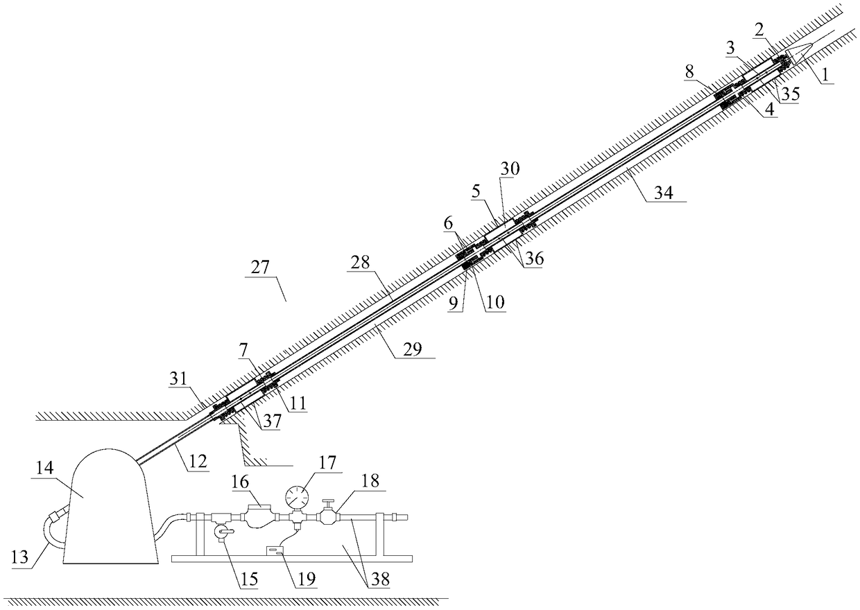
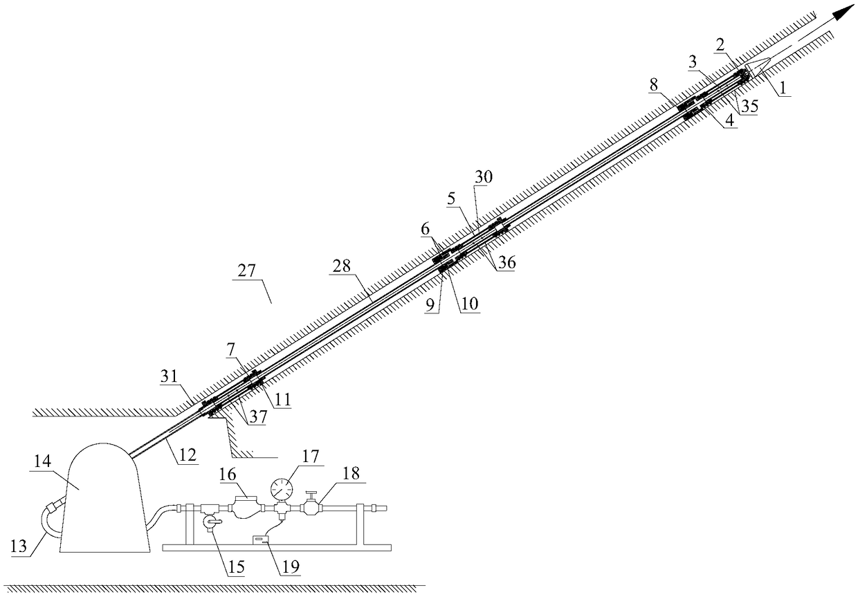
[0057] A segmented observation system for mining damage zones on the roof and floor of a mine, including a test probe, a control console 38, a drilling rig 14 and a drill pipe 12;

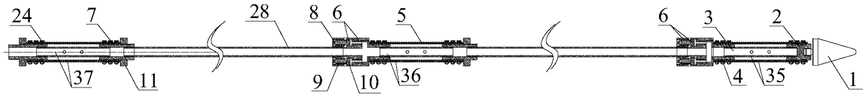
[0058] Described test probe comprises occluder, converter 6 and connecting pipe 28, and occluder comprises front part occluder 35, middle part occluder 36, tail end occluder 37; The joints at both ends of the leaking pipe and the rubber bag 5, the rubber bag 5 is wrapped around the periphery of the leaking pipe 3, forming a sealing cavity 30 with the leaking pipe 3, and the external water source is injected into the sealing cavity 30 through the leaking hole 25 to swell the rubber The capsule 5 forms a water injection cavity with the borehole 31;

[0059] The drilling rig 14 is connected with the test probe through the drill ro...


PUM


Abstract

The invention discloses a mine roof-to-floor mining damage zone subsection observation method, and belongs to the technical field of rock mass damage range determination. A used observation system includes a test probe, a drilling rig, a drilling pipe and a control console. The test probe includes a front portion plugging device, a tail portion plugging device, a converter and a communicating pipe. The plugging device comprises a leaky pipe, connectors connected to the two ends of the water leakage pipe and a rubber capsule, the rubber capsule is wrapped around the periphery of the water leakage pipe, a sealing cavity is formed between the rubber capsule and the water leakage pipe, a sealing cavity is injected with an external water source to expand the rubber capsule, and a water injection cavity is formed with the drilling hole. The test device can use the same external water source to complete the plugging process and test process and achieves variable control of high and low waterpressure, the two work under the required pressure is ensured, the winding problem of the drilling pipe and a hose is eliminated, the operation steps and number of workers are reduced, and the efficiency of propulsion measurement is improved.

Description

technical field [0001] The invention belongs to the technical field of rock mass damage range measurement, and in particular relates to a segmented observation method for mine roof and floor mining damage zones. Background technique [0002] The measurement of the range and permeability of the rock mass mining fracture zone is the basic parameter for studying the failure characteristics of the rock mass. It is of great significance for further exploring the relationship between it and the movement law and stress field of the rock mass. Variable electromagnetic method, microseismic detection and pressure water test method. Among them, the pressure water test method is the most reliable. The traditional device "double-ended side leakage device" is used to conduct water injection and discharge tests to determine the development height or depth of the rock formation affected by mining. In the traditional device, there are two external systems, the water injection operation plat...

Claims


Application Information

Patent Timeline
Patent Type & Authority Applications(China)
IPC IPC(8): E21B49/00
CPCE21B49/008
Inventor 梁正召宋文成高敏唐世斌马天辉钱希坤薛瑞雄
Owner DALIAN UNIV OF TECH
Why Eureka
Try Eureka