Eureka AIR delivers breakthrough ideas for toughest innovation challenges, trusted by R&D personnel around the world.

In situ testing method of rock mass permeability

An in-situ test and permeability technology, which is applied in the fields of permeability/surface area analysis, measurement device, suspension and porous material analysis, etc., can solve the problem of device blockage observation process, equipment failure, and gas supply pipeline that are easy to break and other problems, to achieve the effect of easy reset in time, sensitive and balanced pressure regulation, and reduce the number of pipelines

Inactive Publication Date: 2020-05-19
DALIAN UNIV OF TECH
View PDF8 Cites 0 Cited by
  • Summary
  • Abstract
  • Description
  • Claims
  • Application Information

AI Technical Summary

Problems solved by technology

Since the two external water supply and gas supply consoles are independent of each other, it is bound to cause the correspondingly connected water supply (for observation) and gas supply (for plugging) two pipelines to occur as the test probe advances in the drilling process. The two pipes are entangled with each other, which may cause the device to be blocked or the observation process to be unstable, or the gas supply pipe may be easily broken, causing the equipment to fail to work normally.
How to integrate the plugging and supply operation platform into one, reduce the number of pipelines in the borehole, and at the same time make the plugging process and the observation process work under their respective pressures and maintain the real-time replenishment process, the existing technology fails to solve the above problems at the same time

Method used


Image

  • In situ testing method of rock mass permeability
  • In situ testing method of rock mass permeability
  • In situ testing method of rock mass permeability

Examples


Embodiment Construction

[0051] The present invention will be described in further detail below in conjunction with specific embodiments.

[0052] An in-situ test device for rock mass permeability, which mainly includes a test probe, a propulsion mechanism, and a control mechanism;

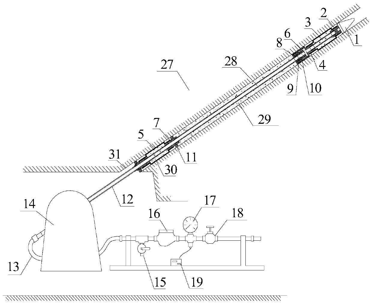
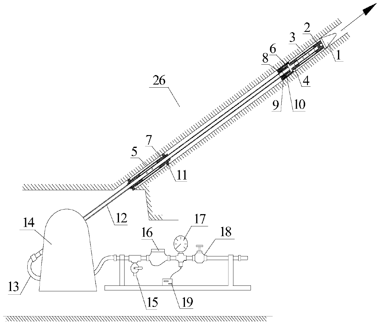
[0053] Such as Figure 1-3 As shown, the test probe includes a rubber bag 5, a leaking pipe 3, a converter 6, and a connecting pipe 28. The two ends of the leaking pipe 3 are respectively connected to joint one 2, joint two 4 or joint three 7. The periphery of the leaking water pipe 3 between the joints is surrounded by a rubber bag 5, and a certain plugging cavity 30 is formed between the rubber bag 5 and the leaking water pipe 3. The inside of the converter 6 is provided with a conical conversion body 10, and the inside and surface of the conical conversion body 10 are respectively provided with a water hole 23 and an annular water tank 22, forming a water leakage channel with the first hole 20 on the converter 6.

[...


PUM

PropertyMeasurementUnit
diameteraaaaaaaaaa
lengthaaaaaaaaaa

Abstract

The invention belongs to the technical field of rock body destroy range and permeability test and discloses an in-situ testing method for permeability of a rock body. The device comprises a testing probe, a propelling mechanism and a control mechanism, wherein the testing probe comprises a rubber capsule, a drain pipe, a converter and a communicating pipe; two ends of the drain pipe are separatelyconnected to a joint I, a joint II or a joint III; the rubber capsule winds the periphery of the drain pipe between the two joints, and a certain plugging cavity is formed between the rubber capsuleand the drain pipe. A cone-shaped converting body is arranged in the converter; a water through hole and an annular water channel are formed in the cone-shaped converting body and in the surface of the cone-shaped converting body, separately to from a drain channel with a hole I in the converter. The testing device can work under pressures of a same water source in a plugging process and a testingprocess by converting from plugging a high pressure water source to observing a low pressure water source, so that the quantity of the pipeline in the drilled hole is one. The winding problem of a drill pipe and a hose is solved, and the stability of the working process is improved.

Description

technical field [0001] The invention belongs to the technical field of rock mass damage range and permeability measurement, and in particular relates to an in-situ test method for rock mass permeability. Background technique [0002] The permeability of rock mass is an important parameter to reflect the failure characteristics of rock mass. The change of rock mass permeability is closely related to its failure. Exploring its permeability change can further judge the damage range of rock mass. It is very important for further research on rock mass failure mechanism and water inrush mechanism is of great significance. At present, the commonly used methods for detecting the damage range of rock mass include direct current method, transient electromagnetic method, microseismic detection and pressure water test method. Since the direct current method and the transient electromagnetic method are easily affected by the electromagnetic field of the working environment, and the micr...

Claims


Application Information

Patent Timeline
Patent Type & Authority Patents(China)
IPC IPC(8): G01N15/08
CPCG01N15/082G01N15/088
Inventor 宋文成梁正召张轩唐世斌马天辉武娜钱希坤
Owner DALIAN UNIV OF TECH
Why Eureka
Eureka Blog
Learn More