Control structure of a shifting fork

A shift fork and control structure technology, which is applied in the field of automobile transmission, can solve the problems of large space in the transmission, low precision of gear selection, and large radial area occupied, and achieve small space requirements, improve assembly cycle, and diameter Towards a small effect

Pending Publication Date: 2018-10-12
SUZHOU DONGFENG FINEBLANKING ENG
View PDF7 Cites 1 Cited by
  • Summary
  • Abstract
  • Description
  • Claims
  • Application Information

AI Technical Summary

Problems solved by technology

[0002] In the existing transmission manipulation technology, the shift fork shafts and shift forks are arranged in one-to-one correspondence, which makes the number of shift fork shafts larger and the space required by the transmission is large; when one shift fork shaft corresponds to multiple shift forks After the shift fork technology, it is necessary to set up an interlock mechanism. However, the combination of the existing interlock mechanism and the shift fork shaft occupies a large radial area, and the selection and shifting accuracy is not high.

Method used


Image

  • Control structure of a shifting fork
  • Control structure of a shifting fork
  • Control structure of a shifting fork

Examples


Embodiment Construction

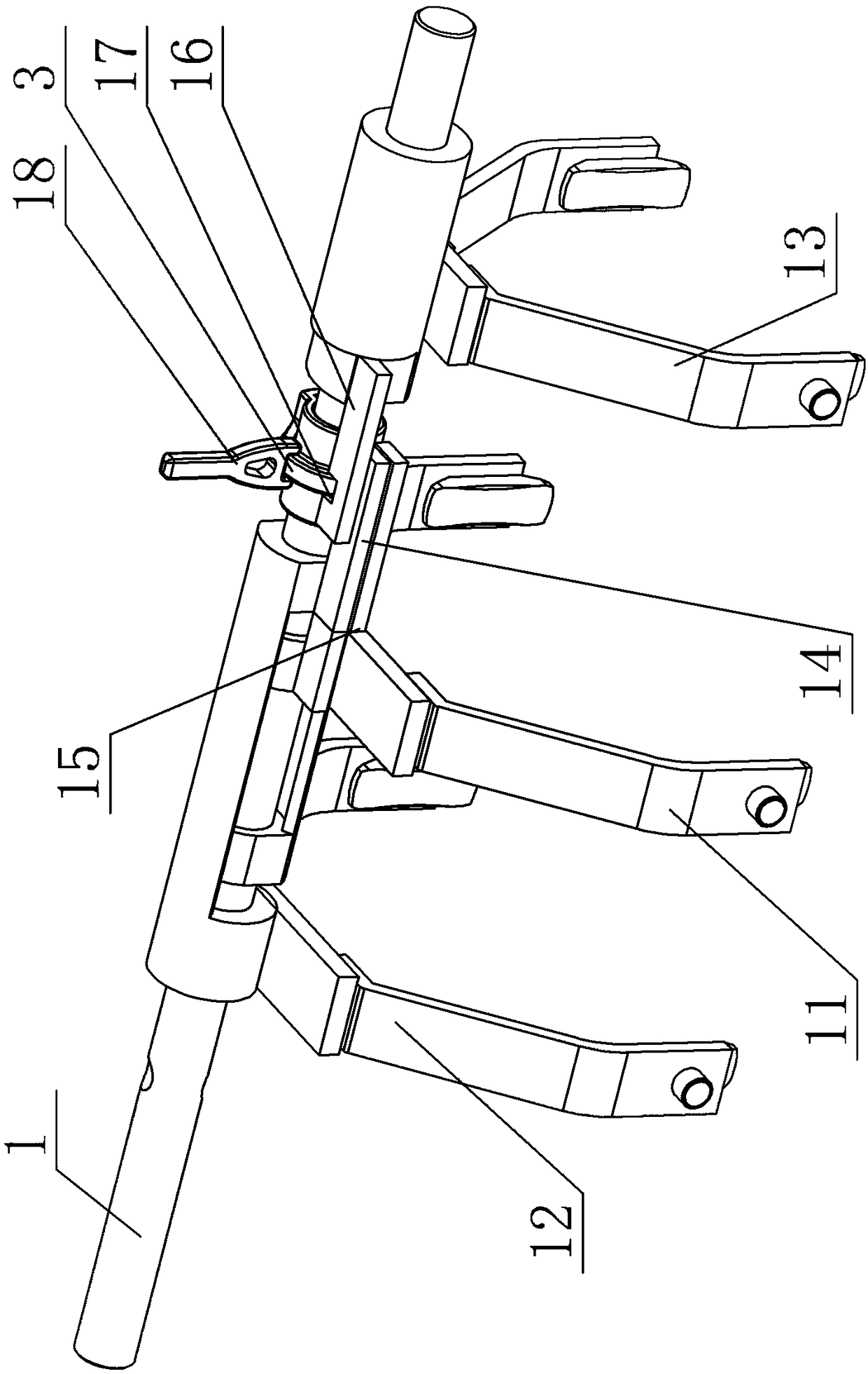
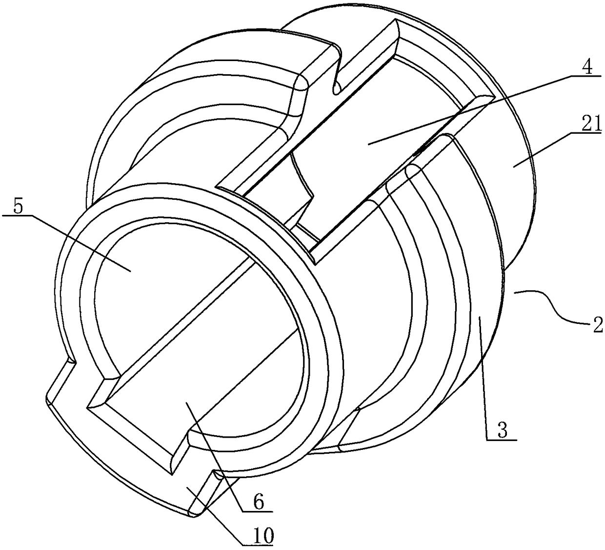
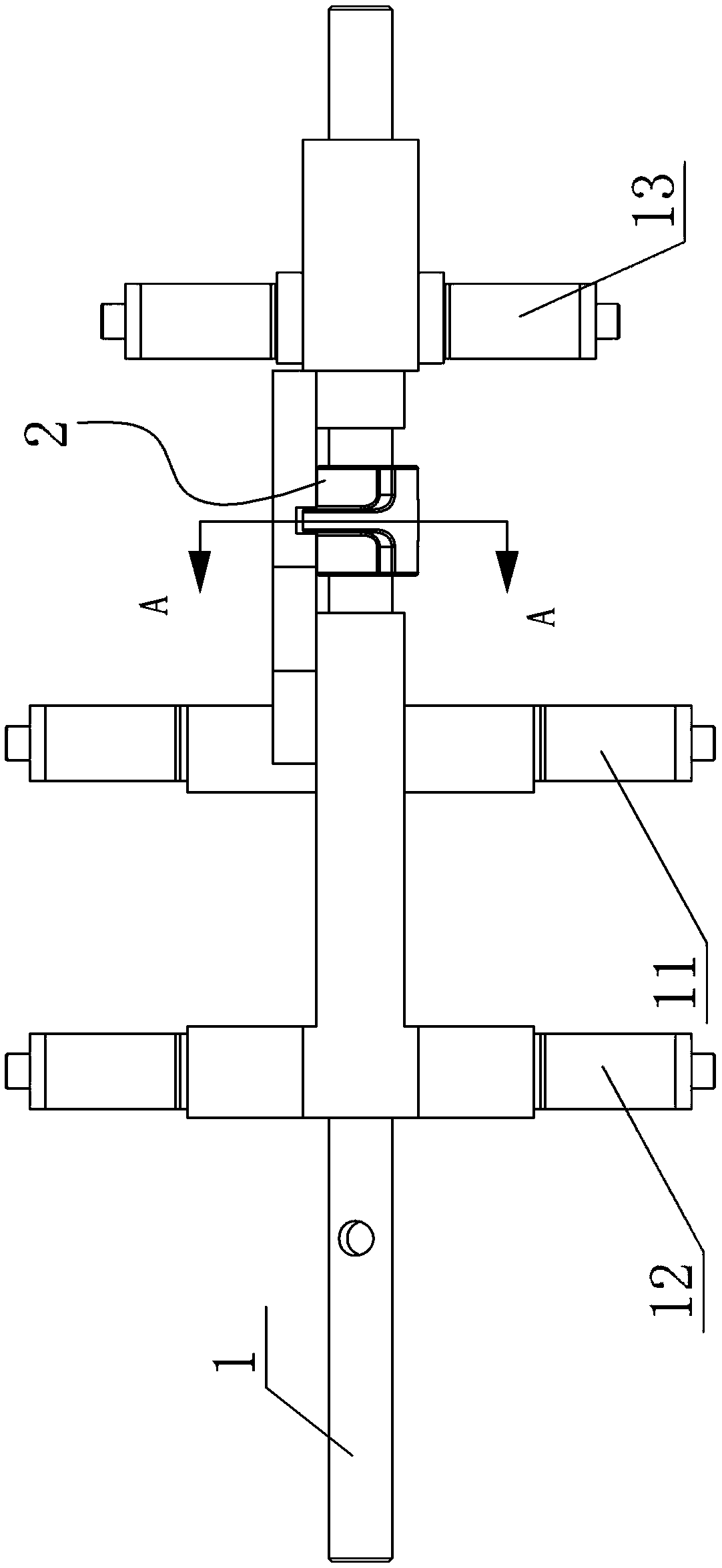
[0024] A control structure for a shift fork, see Figure 1-Figure 6 : It includes a shift fork shaft 1, an interlock device 2, and several shift forks, the input connection parts of several shift forks are respectively set on the shift fork shaft 1, and the input connection parts of the shift forks are correspondingly provided with axial The shift fork slot plates arranged in length, each shift fork slot plate is arranged at different radial positions of the shift fork shaft 2, and all the shift fork slot plates are respectively provided with shift forks corresponding to one axial length position of the shift fork shaft 2 Groove 17, the interlocking device 2 is set in the area of ​​the shifting fork groove corresponding to the shifting fork groove 1, the interlocking device 2 includes an annular boss 3, and the annular boss 3 is clamped to the shifting fork groove 17 The corresponding shift fork slot plate is locked, and the interlocking device 2 also includes an open groove 4...


PUM


Abstract

The invention provides a control structure of a shifting fork. The control structure of the shifting fork is capable of ensuring the selecting and shifting accuracy of the whole structure, and is small in radial range and facilitates the reasonable arrangement of a gearbox. The control structure of the shifting fork comprises a shifting fork shaft, an interlocking device and a plurality of shifting forks, wherein the input connecting parts of the plurality of shifting forks correspondingly sleeve the shifting fork shaft; shifting fork slot plates which are arranged along the axial length are correspondingly mounted at the input connecting parts of the shifting forks; the shifting fork slot plates are arranged at different radial positions on the shifting fork shaft; each shifting fork slotplate is provided with a shifting fork concave slot at a position corresponding to the axial length of the shifting fork shaft; the interlocking sleeve sleeves a corresponding area in the shifting fork concave slots; the interlocking device comprises an annular boss which is used for locking the corresponding shifting fork slot plate by clamping the shifting fork groove; and the interlocking device further comprises an opening slot which is formed in the surface, and a guide sunken groove which is formed in the inner wall of the through hole.

Description

technical field [0001] The invention relates to the technical field of automobile transmission, in particular to a control structure for a shift fork. Background technique [0002] In the existing transmission manipulation technology, the shift fork shafts and shift forks are arranged in one-to-one correspondence, which makes the number of shift fork shafts larger and the space required by the transmission is larger; when one shift fork shaft corresponds to multiple shift forks After the technology of the shift fork, an interlock mechanism needs to be provided. However, the combination of the existing interlock mechanism and the shift fork shaft occupies a large radial area, and the selection and shifting accuracy is not high. Contents of the invention [0003] In view of the above problems, the present invention provides a control structure of a shift fork, which can ensure the accuracy of the entire structure in selecting and shifting, and has a small radial range, which...

Claims


Application Information

Patent Timeline
Patent Type & Authority Applications(China)
IPC IPC(8): F16H63/32F16H63/36
CPCF16H63/32F16H63/36F16H2063/3076F16H2063/3083
Inventor 张敏袁立立伍超军钱清管伟
Owner SUZHOU DONGFENG FINEBLANKING ENG
Why Eureka
Try Eureka