
Wind and gas control system for fuel gas stove

A control system and gas stove technology, applied in the direction of burner, combustion method, heating fuel, etc., can solve problems such as burns and scalds, and achieve the effects of avoiding potential safety hazards, convenient use, and simple structure

Active Publication Date: 2018-10-12
ANHUI HANSUM INSTR EQUIP
View PDF6 Cites 1 Cited by
  • Summary
  • Abstract
  • Description
  • Claims
  • Application Information

AI Technical Summary

Problems solved by technology

If the chef does not escape in time, he will be easily burned and scalded. At the same time, the flame can easily ignite the oil accumulated in the range hood above the stove, causing a fire

Method used


Image

  • Wind and gas control system for fuel gas stove
  • Wind and gas control system for fuel gas stove
  • Wind and gas control system for fuel gas stove

Examples


Embodiment Construction

[0043] Below in conjunction with embodiment technical solution of the present invention is made more specific description:

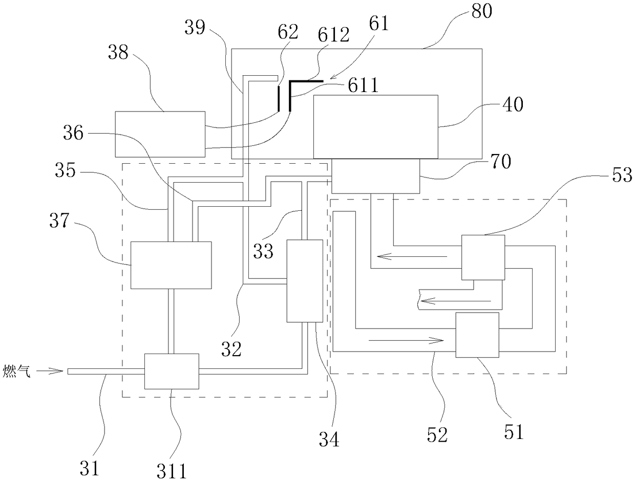
[0044] Such as figure 1 As shown: the present invention includes a gas circuit unit, and the gas circuit unit includes a main gas circuit 31 and an automatic ignition gas circuit unit and a manual ignition gas circuit unit respectively communicated with the general gas circuit 31 . The main gas circuit 31 is provided with a gas main valve 311 for switching gas to the automatic ignition gas circuit unit or the manual ignition gas circuit unit.

[0045] 1-Manual ignition gas circuit unit

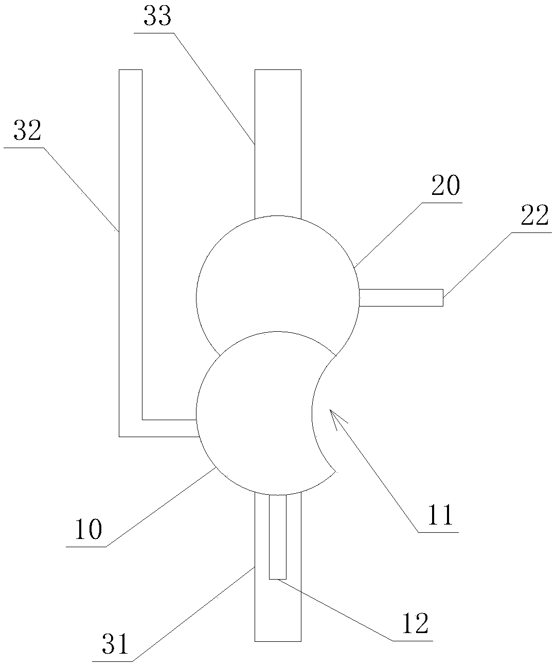
[0046] Such as figure 2 As shown: when the second notch 21 is at the 6 o'clock position directly below the second turntable, and when the first notch 11 is at the 3 o'clock position of the first turntable, the permanent flame gas circuit valve And the main fire gas path valve is in the initial closed state, the edge of the first turntable 10 coincides with the second...


PUM


Abstract

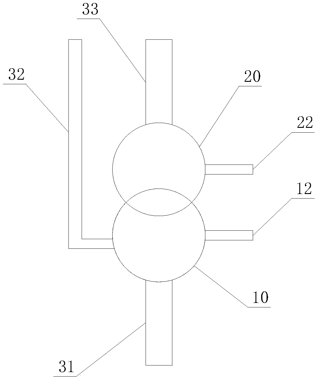
The invention relates to a wind and gas control system for a fuel gas stove. The wind and gas control system comprises an automatic ignition gas path unit and a manual ignition gas path unit; the manual ignition gas path unit comprises a pilot flame gas path and a main flame gas path; a first rotary disc used for controlling a pilot flame gas path valve is arranged on the pilot flame gas path; a second rotary disc used for controlling a main flame gas path valve is arranged on the main flame gas path; a first notch is formed in the first rotary disc; a second notch is formed in the second rotary disc; when the edge of the first rotary disc is clamped in the second notch and limits rotation of the second rotary disc, the pilot flame gas path valve and the main flame gas path valve are at aninitial closing state; when the first rotary disc rotates until the first notch and the second notch are opposite and limiting of rotation of the second rotary disc is relieved, the pilot flame gas path valve is at an opening state; and when the second rotary disc rotates until the edge of the second rotary disc is clamped in the first notch to limit rotation of the first rotary disc, the main flame gas path valve is at an opening state. By adopting the wind and gas control system, manual ignition of the stove is safely realized.

Description

technical field [0001] The invention belongs to the technical field of gas cookers, and in particular relates to an air control system for a gas cooker. Background technique [0002] Generally, automatic ignition stoves are provided with a pilot flame, and the pilot flame is kept for a long time during the working period of the stove to ignite the main fire when needed. The atmosphere control system of the automatic ignition stove includes an automatic ignition gas path, and the automatic ignition gas path includes an eternal flame gas path that communicates with the main gas path and supplies gas to the permanent flame respectively, and a main fire gas path that supplies gas to the main fire, An automatic ignition gas path control valve is installed on the main gas path to generate linkage control with the ignition control part, that is, the ignition control part sends an ignition signal, and the automatic ignition gas path control valve automatically opens and sends to the...

Claims


Application Information

Patent Timeline
Patent Type & Authority Applications(China)
IPC IPC(8): F24C3/12F24C3/10F23D14/02
Inventor 夏光超
Owner ANHUI HANSUM INSTR EQUIP
Learn More