Pneumatic control device and hopper truck

A pneumatic control and control box technology, applied in the hydraulic field, can solve problems such as safety hazards and misoperation

Active Publication Date: 2013-04-03
CRRC QIQIHAR ROLLING CO LTD
View PDF4 Cites 8 Cited by
  • Summary
  • Abstract
  • Description
  • Claims
  • Application Information

AI Technical Summary

Problems solved by technology

[0005] From the above content, it can be seen that when the travel switch is turned on and off, it needs to be trigger

Method used


Image

  • Pneumatic control device and hopper truck

Examples


Embodiment Construction

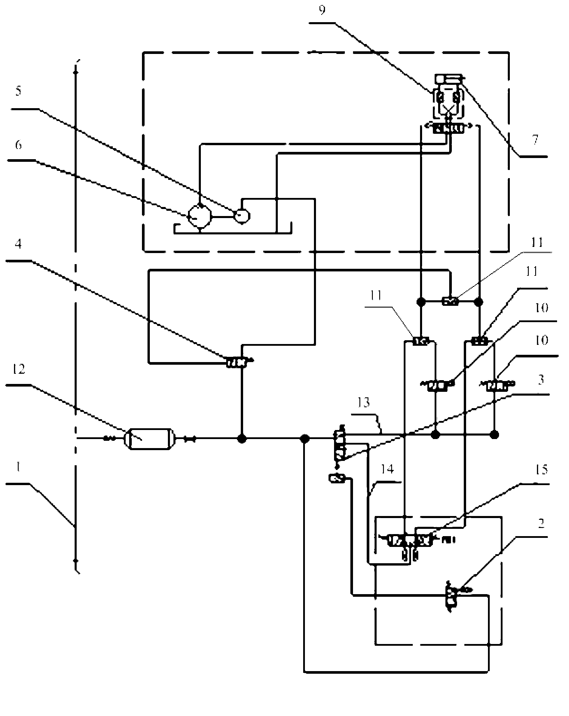
[0026] figure 1 It is a schematic diagram of the principle of the pneumatic control device provided by the embodiment of the present invention.

[0027] The embodiment of the present invention provides a pneumatic control device, which includes a control box, an air storage cylinder 12, a travel switch 2, a two-position five-way reversing valve 3, an air control reversing valve 10, a three-position five-way reversing valve 15, Shuttle valve 11, two-position two-way solenoid valve 4, air motor 5, hydraulic pump 6 and hydraulic cylinder 7. The control box has a box door; the air storage cylinder 12 is used to connect with the brake air pipe 1; the travel switch 2 is connected with the air storage cylinder 12; the two-position five-way reversing valve 3 is connected with the travel switch 2, and the The two communication positions of the two-position five-way reversing valve 3 correspond to the first branch 13 and the second branch 14 respectively; the air control reversing valv...


PUM


Abstract

The invention provides a pneumatic control device and a hopper truck. The pneumatic control device comprises a control box, a wind storage cylinder, a stroke switch, a two-position five-way reversing valve, a wind control reversing valve, a three-position five-way reversing valve, a shuttle valve, a two-position two-way electromagnetic valve, a pneumatic motor, a hydraulic pump and a hydraulic oil cylinder. Two communication positions of the two-position five-way reversing valve respectively correspond to a first branch and a second branch. When a box door of the control box is opened, the stroke switch is in the communicated position, and the two-position five-way reversing valve breaks the first branch and opens the second branch. The three-position five-way reversing valve is manually controlled to control expansion of the hydraulic oil cylinder. When the box door of the control box is closed, the stroke switch is in the disconnected position, and the two-position five-way reversing valve communicates the first branch and disconnects the second branch. The hydraulic oil cylinder is automatically controlled to expand by the wind control reversing valve. According to the pneumatic control device, the two branches can be interlocked, so that the safety of the pneumatic control device is improved.

Description

technical field [0001] The invention relates to hydraulic technology, in particular to a pneumatic control device and a hopper truck. Background technique [0002] The funnel truck is used to transport goods. Taking the bottom door hopper truck as an example, the opening or closing of the bottom door is controlled by a pneumatic control device. [0003] Specifically, the pneumatic control device includes a control box, a brake air duct, an air storage cylinder connected to the brake air duct, a travel switch connected to the air storage cylinder, a two-position five-way reversing valve connected to the travel switch, and a The air control reversing valve connected to the two-position five-way reversing valve, the shuttle valve connected to the air control reversing valve, the two-position two-way solenoid valve connected to the shuttle valve, the air motor connected to the two-position two-way solenoid valve, A hydraulic pump connected with the air motor, a two-way hydrauli...

Claims


Application Information

Patent Timeline
IPC IPC(8): B61D7/28B61H11/06F15B21/00
Inventor 于凤辉张俊林赵天军付勇
Owner CRRC QIQIHAR ROLLING CO LTD
Why Eureka
Try Eureka