
Signal transmission method, receiving end, transmitting end and terminal equipment

A technology for signal transmission and transmission, which is applied in the field of communication and can solve the problems of reducing the sensing area, reducing the power of electrical signals, and reducing the charging efficiency of terminal equipment.

Active Publication Date: 2018-10-12
VIVO MOBILE COMM CO LTD
View PDF2 Cites 7 Cited by
  • Summary
  • Abstract
  • Description
  • Claims
  • Application Information

AI Technical Summary

Problems solved by technology

[0004] However, in the above method, in the process of charging the terminal device, if the induction area between the wireless charging transmitter and the terminal device is reduced due to the offset or movement of the terminal device, then the electrical signal sent by the wireless charging transmitter The power may also be reduced, which may reduce the actual power received by the terminal device, thereby reducing the charging efficiency of the terminal device

Method used


Image

  • Signal transmission method, receiving end, transmitting end and terminal equipment
  • Signal transmission method, receiving end, transmitting end and terminal equipment
  • Signal transmission method, receiving end, transmitting end and terminal equipment

Examples


Embodiment Construction

[0023] The following will clearly and completely describe the technical solutions in the embodiments of the present invention with reference to the accompanying drawings in the embodiments of the present invention. Obviously, the described embodiments are some of the embodiments of the present invention, but not all of them. Based on the embodiments of the present invention, all other embodiments obtained by persons of ordinary skill in the art without creative efforts fall within the protection scope of the present invention.

[0024] The terms "first" and "second" in the description and claims of the embodiments of the present invention are used to distinguish different objects, rather than to describe a specific sequence of objects. In the description of the embodiments of the present invention, unless otherwise specified, "plurality" means two or more.

[0025] The term "and / or" in this article is an association relationship describing associated objects, which means that ...


PUM


Abstract

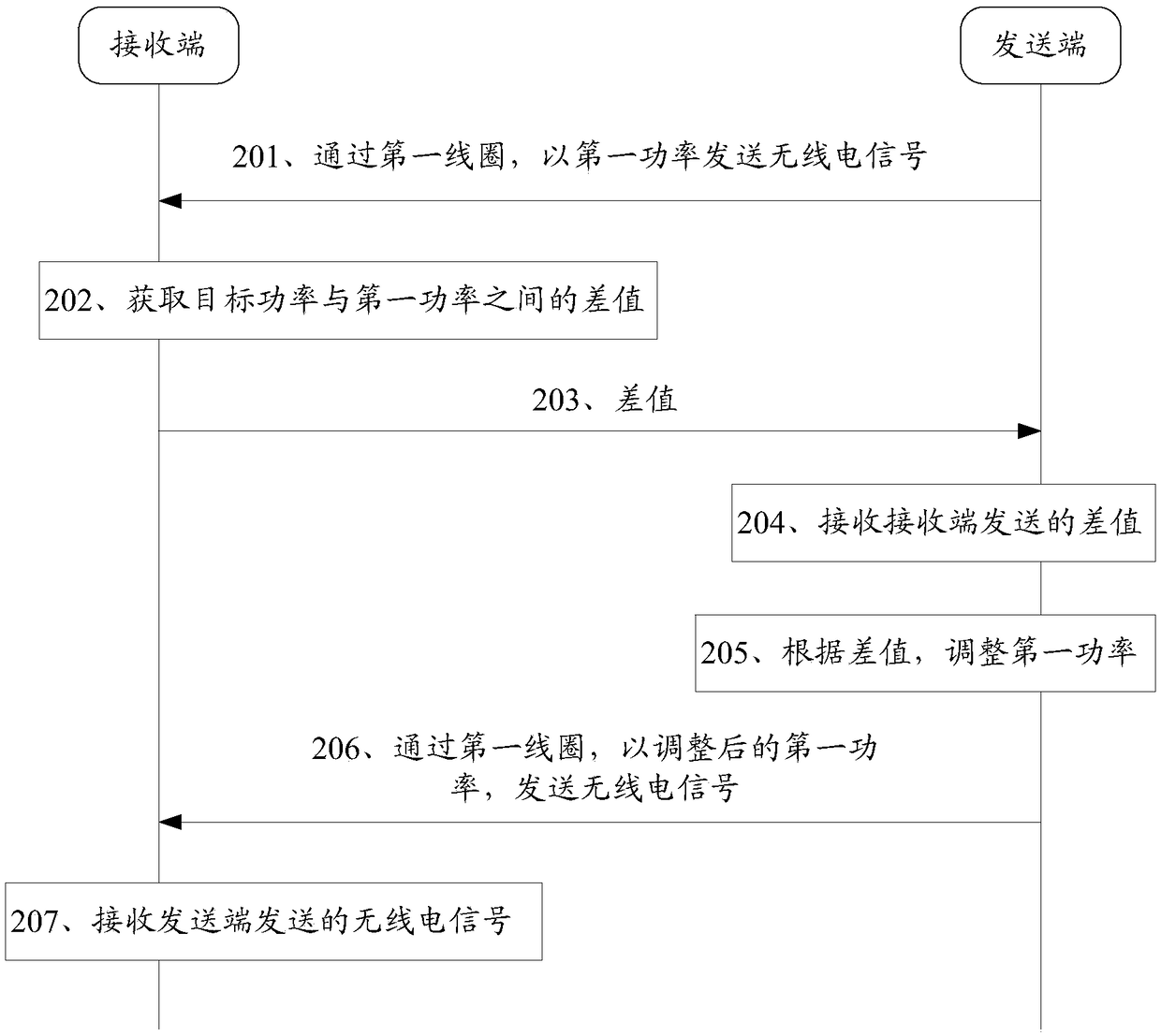
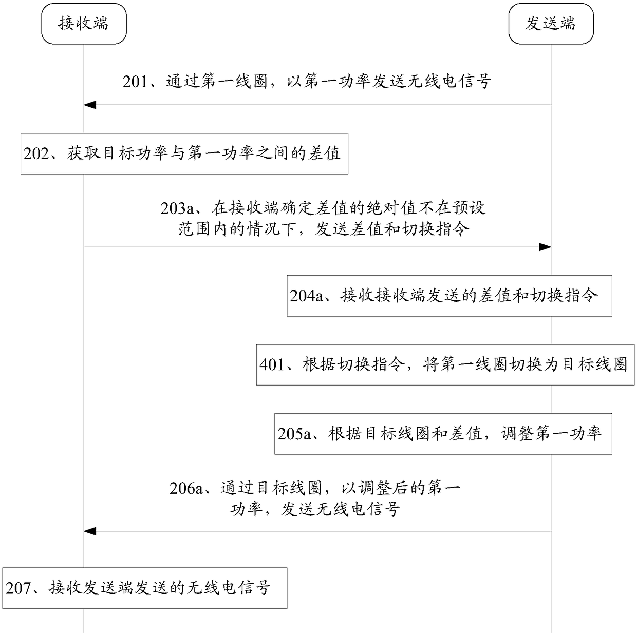
Embodiments of the invention disclose a signal transmission method, a receiving end, a transmitting end and terminal equipment, relate to the technical field of communication, and can solve the problem of lowering of charging efficiency of the terminal equipment caused by lowering of actual power received by the terminal equipment due to a reduced induction area of a wireless charging transmitterand the terminal equipment when the terminal equipment suffers from offset or movement in the charging process of the terminal equipment. According to a specific scheme: the receiving end obtains a difference value between target power and first power, wherein the target power is power requested by the receiving end from the transmitting end, and the first power is power of a wireless electric signal transmitted to the receiving end by the transmitting end according to the target power; the receiving end transmits the difference value to the transmitting end, wherein the absolute value of thedifference value is not within a preset range, and the difference value is used for allowing the transmitting end to adjust the first power; and the receiving end receives the wireless electric signalfrom the transmitting end, and the power of the wireless electric signal is the adjusted first power.

Description

technical field [0001] The embodiments of the present invention relate to the technical field of communications, and in particular, to a signal transmission method, a receiving end, a sending end, and a terminal device. Background technique [0002] Wireless charging technology is a new technology based on the principle of electromagnetic induction. A wireless charging transmitter based on wireless charging technology can charge terminal devices without a charging power cord. Generally, a wireless charging transmitter includes one or more primary coils, and when the wireless charging transmitter is working, only one of the primary coils can be activated at a time. [0003] At present, most wireless charging transmitters include three primary coils, two of which are placed side by side, and another primary coil is stacked in the middle of the two primary coils. After the user places the terminal device on the wireless charging transmitter, the wireless charging transmitter c...

Claims


Application Information

Patent Timeline
Patent Type & Authority Applications(China)
IPC IPC(8): H02J50/80H04W52/24
CPCH02J50/80H04W52/245
Inventor 巫志文
Owner VIVO MOBILE COMM CO LTD
Learn More