
Screw placing guide plate for spine and manufacturing method of screw placing guide plate

A manufacturing method and a technology for placing nails, which are applied in the medical field, can solve the problems of high price of real-time navigation system equipment, complicated operation of navigation nail placement, and difficulty in widespread use, so as to reduce the risk of nail placement, shorten the operation time, and facilitate popularization and application. Effect

Pending Publication Date: 2018-10-16
深圳市美创医核医疗科技股份有限公司 +1
View PDF2 Cites 3 Cited by
  • Summary
  • Abstract
  • Description
  • Claims
  • Application Information

AI Technical Summary

Problems solved by technology

[0004] Manual nail placement relies too much on the physician's clinical experience and subjective feeling, lacks the control of objective indicators, and the surgical risk is relatively high; the operation of computer-aided navigation nail placement is very complicated, and the real-time navigation system equipment during the operation is expensive, and it is difficult to be widely used

Method used


Image

  • Screw placing guide plate for spine and manufacturing method of screw placing guide plate
  • Screw placing guide plate for spine and manufacturing method of screw placing guide plate
  • Screw placing guide plate for spine and manufacturing method of screw placing guide plate

Examples


Embodiment Construction

[0029] The present invention will be further described in detail below with reference to the accompanying drawings and in combination with specific embodiments.

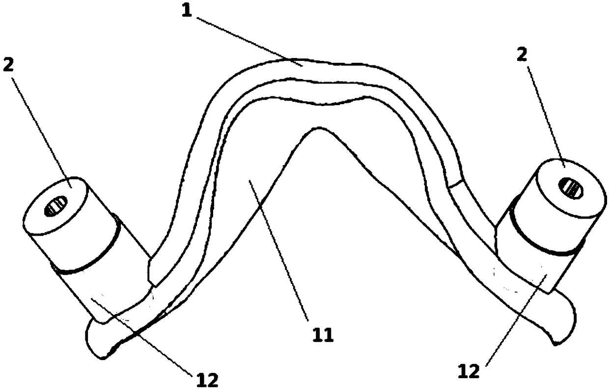
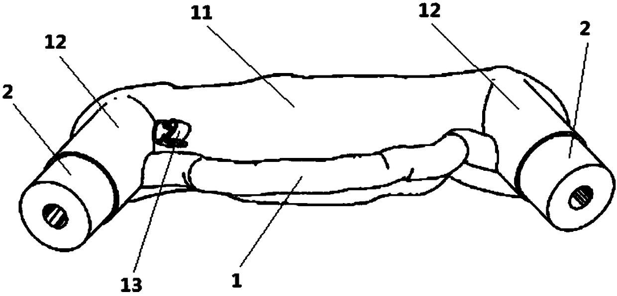
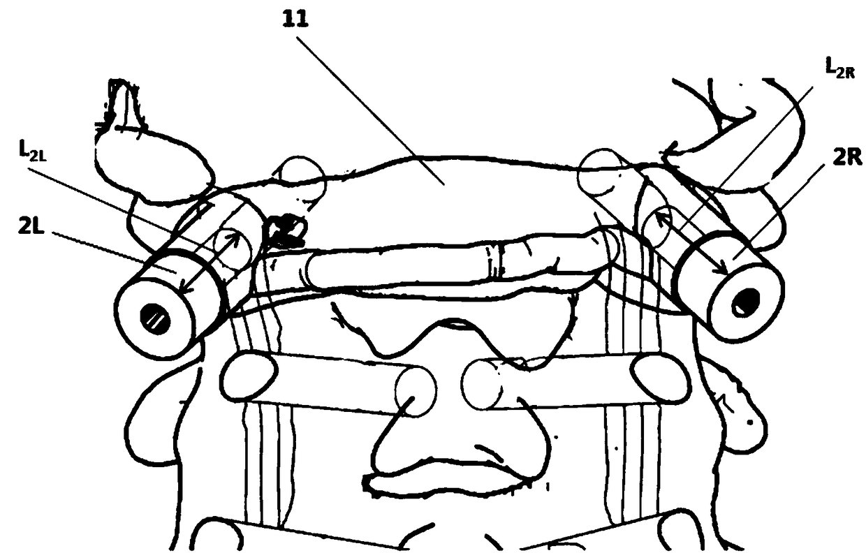
[0030] Such as figure 1 and figure 2 As shown, a guide plate for spinal nail placement provided by an embodiment of the present invention includes a fitting plate 1 and a nail setting sleeve 2. The fitting plate 1 includes a fitting locking part 11 and a guide part 12. The fitting locking part 11 and the The outer surface of the spine in the patient's spinal nailing area is fit and clamped; the guide part 12 is a columnar guide hole arranged on the left and right sides of the fitting board to determine the position and angle of the nailing channel. The guide hole on the side is fixedly connected, and the axial direction is consistent with the guide hole axis. The bottom end of the nail setting sleeve 2 is inserted into the guide hole, and the top is higher than the guide hole by a certain height. The open-circuit ...


PUM


Abstract

The invention discloses a screw placing guide plate for the spine and a manufacturing method of the screw placing guide plate. The screw placing guide plate for the spine comprises an attaching plateand screw placing sleeves, wherein the attaching plate comprises an attaching clamping part and guide parts; the attaching clamping part is in attaching clamping with the outer surface of the spine ina screw placing area for the spine of a patient; the guide parts are cylinder-shaped guide holes arranged in the left and right sides of the attaching plate, and then the position and angle of a screw placing channel for placing a screw into the spine of the patient are determined. The screw placing sleeves are fixedly connected with the guide holes in two sides of the attaching plate, the axialdirection is consistent with the axial direction of the guide holes, the bottom ends of the screw placing sleeves are arranged inside the guide holes, and the top ends of the screw placing sleeves arehigher than the guide holes by certain height. In the screw placing surgery, an opening cone is used for drilling inside the spine of the patient along the axial direction of the screw placing sleeves, then the screw placing channel is established, the screw is placed in the spine of the patient along the screw placing channel, and then the screw placing surgery is completed. With the screw placing guide plate for the spine, the screw placing is accurate in position and is safe, the surgical risk can be effectively reduced, the surgical time can be shortened, and the guide plate is convenientfor popularization and application, and has the obvious application value.

Description

technical field [0001] The invention relates to the field of medical technology, in particular to a guide plate for spinal nail placement and a manufacturing method thereof. Background technique: [0002] The spinal canal houses the spinal cord, and important nerves and blood vessels pass through the transverse foramina and intervertebral foramen. In spinal surgery, due to exposure, doctors often only see a plane instead of a three-dimensional structure, and the identifiable anatomical landmarks are limited. The process of using open-circuit cones to establish the screw channel must be precise. Once the open-circuit cone is drilled or the screw is placed in the wrong direction or depth, it will damage the blood vessel and nerve structure, resulting in tragic consequences. [0003] In traditional spinal surgery, manual screw placement is usually used. By observing CT (Computed Tomography, computerized tomography), MR (Magnetic Resonance, magnetic resonance), X-ray and other...

Claims


Application Information

Patent Timeline
Patent Type & Authority Applications(China)
IPC IPC(8): A61B17/90
CPCA61B17/88A61B2017/00526A61B2017/564A61B17/90
Inventor 车晓明顾文韬谢嵘寿佳俊刘晓东顾士欣樊佳顺王子龙唐春明
Owner 深圳市美创医核医疗科技股份有限公司
Learn More