Environment-friendly building pipe paint spraying device
An environmentally friendly and architectural technology, applied in the direction of spraying devices, can solve the problems of unsatisfactory painting efficiency, affecting the health of operators, and low efficiency, and achieve the effect of preventing paint mist from drifting, good painting effect and high efficiency
- Summary
- Abstract
- Description
- Claims
- Application Information
AI Technical Summary
Problems solved by technology
Method used
Image
Examples
no. 1 approach
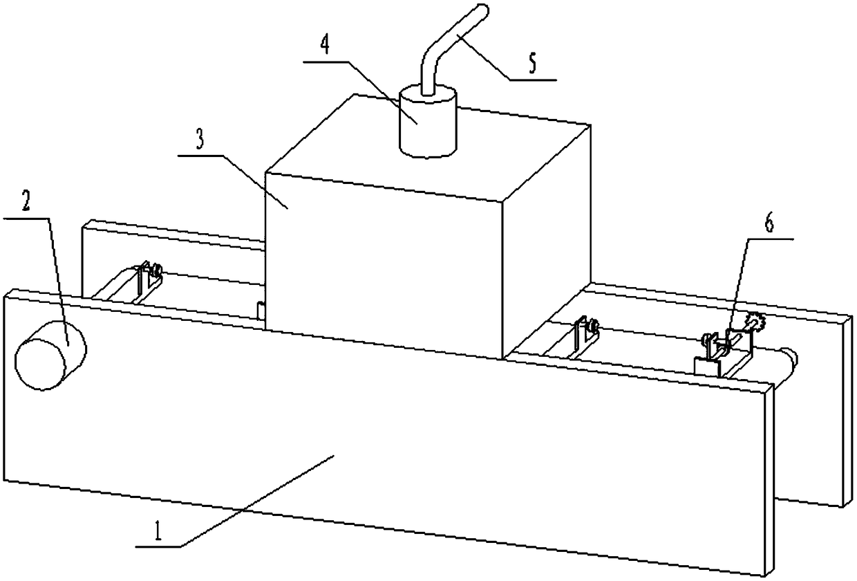
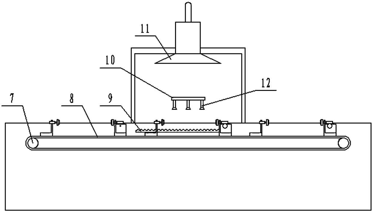
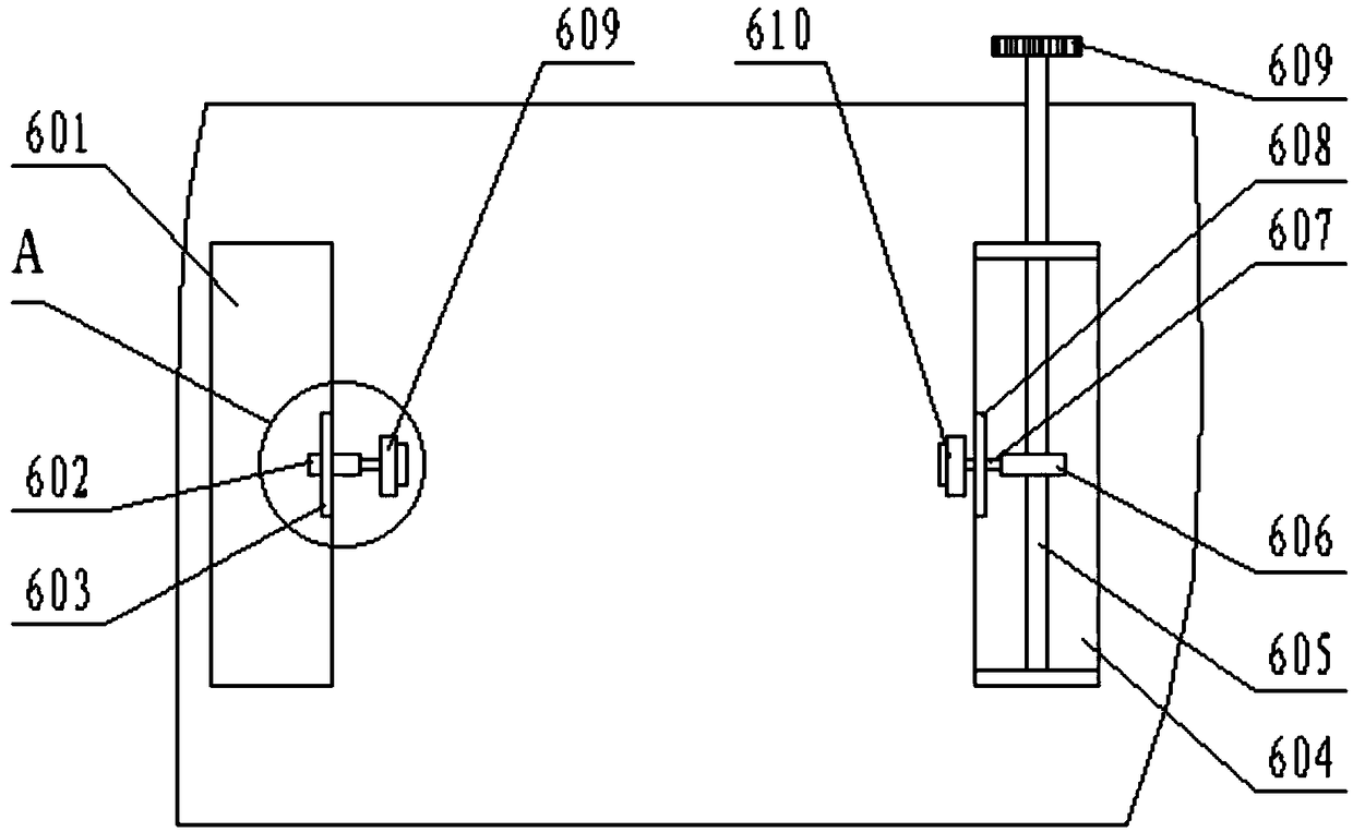
[0027] The first embodiment: see Figure 1-Figure 5 As shown, the present invention provides a kind of environmental protection type construction pipe material spraying device, comprises frame 1, and frame 1 side is equipped with conveying motor 2, and frame 1 inner wall side is equipped with rack 9, and frame 1 is installed with Conveying roller 7, conveying roller 7 is fixedly connected with conveying motor 2, conveying belt 8 is installed on the outside of conveying roller 7, and clamping mechanism 6 is installed on the surface of conveying belt 8;
[0028] A box body 3 is installed on the upper end of the frame 1, an air suction pump 4 is installed on the upper end of the box body 3, the air suction pump 4 communicates with the box body 3, and an exhaust pipe 5 connected to the water tank is installed on the exhaust end of the air suction pump 4 ; A bearing plate 10 is installed inside the box body 3, and a nozzle 12 is installed at the bottom of the bearing plate 10;
[...
no. 2 approach
[0036] The second embodiment: an environment-friendly construction pipe painting device, including a frame 1, characterized in that: a conveying motor 2 is installed on one side of the frame 1, and a rack 9 is installed on one side of the inner wall of the frame 1, A first group of magnets is also arranged on the inner wall parallel to the extending direction of the rack; a conveying roller 7 is installed inside the frame 1, and the conveying roller 7 is fixedly connected with the conveying motor 2, and the outside of the conveying roller 7 A conveyor belt 8 is installed, and a clamping mechanism 6 is installed on the surface of the conveyor belt 8, and a second group of magnets is arranged at the two end positions corresponding to the transmission direction of the conveyor belt 8 on the two inner walls of the frame;
[0037] A casing 3 is installed on the upper end of the frame 1, and an air suction pump 4 is installed on the upper end of the casing 3, and the air suction pump...
PUM
 Abstract
Description
Claims
Application Information
 - R&D
- Intellectual Property
- Life Sciences
- Materials
- Tech Scout
- Unparalleled Data Quality
- Higher Quality Content
- 60% Fewer Hallucinations
Browse by: Latest US Patents, China's latest patents, Technical Efficacy Thesaurus, Application Domain, Technology Topic, Popular Technical Reports.
© 2025 PatSnap. All rights reserved.Legal|Privacy policy|Modern Slavery Act Transparency Statement|Sitemap|About US| Contact US: help@patsnap.com


