
Device for cleaning and drying piston parts

A drying device and parts technology, applied in drying, drying machine, drying gas arrangement, etc., can solve problems such as corrosion, physical injury, object surface cavitation, etc.

Inactive Publication Date: 2018-10-16
丹阳旭铃精密零部件有限公司
View PDF8 Cites 3 Cited by
  • Summary
  • Abstract
  • Description
  • Claims
  • Application Information

AI Technical Summary

Problems solved by technology

In the existing ultrasonic cleaning machines, the higher the power density, the stronger the cavitation effect, the faster the speed, and the better the cleaning effect. Cavitation and corrosion will occur on the surface of the object, which will affect the processing quality of the parts, and the ultrasonic penetration is strong, so when cleaning the parts, it will cause harm to the body of the staff who have been standing next to the cleaning machine for a long time , so how to efficiently and high-quality cleaning precision parts of pistons with holes has become an important research topic

Method used


Image

  • Device for cleaning and drying piston parts
  • Device for cleaning and drying piston parts
  • Device for cleaning and drying piston parts

Examples


Embodiment Construction

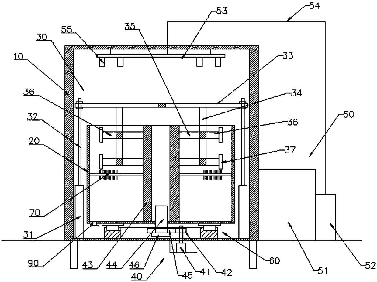
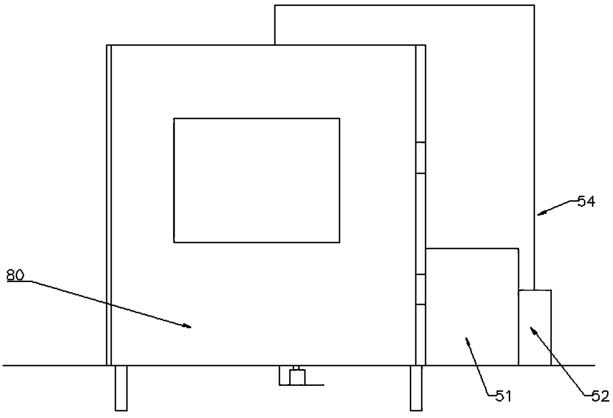
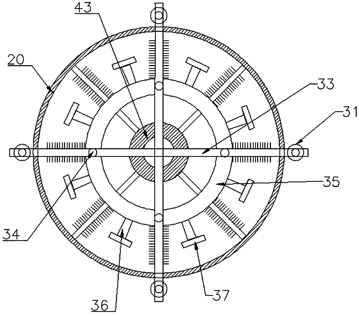
[0022] combine Figure 1 to Figure 4 The shown device for cleaning and drying piston parts, in this embodiment, includes an outer box 10, an inner box 20 located inside the outer box 10, and the inner box 20 and the outer box. The lifting device 30 between 10, the rotating device 40 arranged at the bottom of the inner box 20, and the drying device 50 arranged at the top of the outer box 10, the lifting device 30 includes four cylinders 31, The connecting rod 32 connected to the piston rod of the cylinder 31, the two supporting rods 33 connected to the connecting rod 32 and distributed in a cross shape, the four supporting rods 34 vertically connected to the bottom of the supporting rod 33, and the supporting rods 34 There are two sets of annular hangers 35, the side of the annular hanger 35 away from the shaft core is vertically connected with a number of hanging rods 36, and the end of the hanging rods 36 is connected with a blocking cover 37 by screws. The motor 41 at the b...


PUM


Abstract

The invention provides a device for cleaning and drying piston parts, and belongs to the technical field of part cleaning. The device comprises an outer box, an inner box, a lifting device, a rotatingdevice and a drying device; the lifting device comprises four cylinders annularly arranged on the outer side of the inner box, a connecting rod, two support rods, four supporting rods and at least one set of annular hanging frames; the sides, deviated from mandrels, of the annular hanging frames are vertically connected with multiple hanging rods; the ends of the hanging rods are connected with stop covers through threads; the rotating device comprises a motor, a driving gear, an annular stand column, a rotating shaft, a driven gear, a stop ring fixed at the end part of the rotating shaft, and a support rotating module arranged between the outer box and the inner box; the support rotating module comprises an annular slide rail fixed at the bottom of the outer box, multiple slide blocks cooperating with the slide rail and sliding in the slide rail, and a mounting plate fixed at the tops of the slide blocks; and the mounting plate is connected with the bottom of the inner box. The device is simple in structure, better in cleaning effect and higher in safety.

Description

technical field [0001] The invention belongs to the technical field of parts cleaning, and in particular relates to a device for cleaning and drying piston parts. Background technique [0002] Mechanical parts cleaning machine is a machine that uses ultrasonic waves, organic solvents, etc. to clean parts. In the existing ultrasonic cleaning machine, the higher the power density, the stronger the cavitation effect, the faster the speed, and the better the cleaning effect. Cavitation and corrosion will occur on the surface of the object, thus affecting the processing quality of the parts, and the penetration of ultrasonic waves is strong. Therefore, when cleaning the parts, it will cause harm to the body of the staff who stay next to the cleaning machine for a long time. Therefore, how to efficiently and high-quality cleaning of precision parts with holes has become an important research topic. [0003] Therefore, there is an urgent need for a device for cleaning and drying ...

Claims


Application Information

Patent Timeline
IPC IPC(8): B08B3/08B08B3/10B08B13/00F26B21/00
CPCB08B3/08B08B3/102B08B13/00F26B21/004
Inventor 江川君広
Owner 丹阳旭铃精密零部件有限公司
Learn More