Electric gearbox automatic assembly machine capable of turning to lock screw
What is Al technical title?
Al technical title is built by PatSnap Al team. It summarizes the technical point description of the patent document.
A technology of automatic assembly machine and locking screw mechanism, which is applied in the direction of assembly machine, metal processing, metal processing equipment, etc., can solve the problems of increasing production cost, affecting the effect of assembly, and extruding materials, so as to save electric energy and reduce resonance Possibility, noise reduction effect
Pending Publication Date: 2018-10-16
DONGGUAN XINLIANGDIAN AUTOMATION EQUIP TECH
View PDF7 Cites 2 Cited by
Summary
Abstract
Description
Claims
Application Information
AI Technical Summary
This helps you quickly interpret patents by identifying the three key elements:
Problems solved by technology
Method used
Benefits of technology
Problems solved by technology
[0004] The object of the present invention is to provide an automatic assembly machine for electric gearboxes with variable direction locking screws, so as to solve the problem that the existing automatic assembly machines proposed in the above-mentioned background technology sometimes accumulate materials in the conveying channel of the machine during use, but the machine If it is still working, it may cause the material to squeeze out of the conveying channel, which will affect the effect of assembly, and at the same time, the production cost will increase
Method used
Image
Click on the blue label to locate the original text in one second.
Reading with bidirectional positioning of images and text.
Examples
Embodiment Construction
[0029] The following will clearly and completely describe the technical solutions in the embodiments of the present invention with reference to the accompanying drawings in the embodiments of the present invention. Obviously, the described embodiments are only some, not all, embodiments of the present invention. Based on the embodiments of the present invention, all other embodiments obtained by persons of ordinary skill in the art without making creative efforts belong to the protection scope of the present invention.
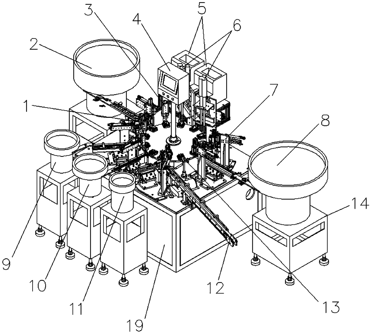
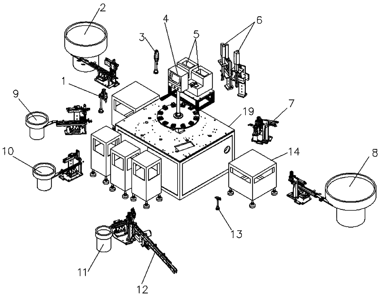
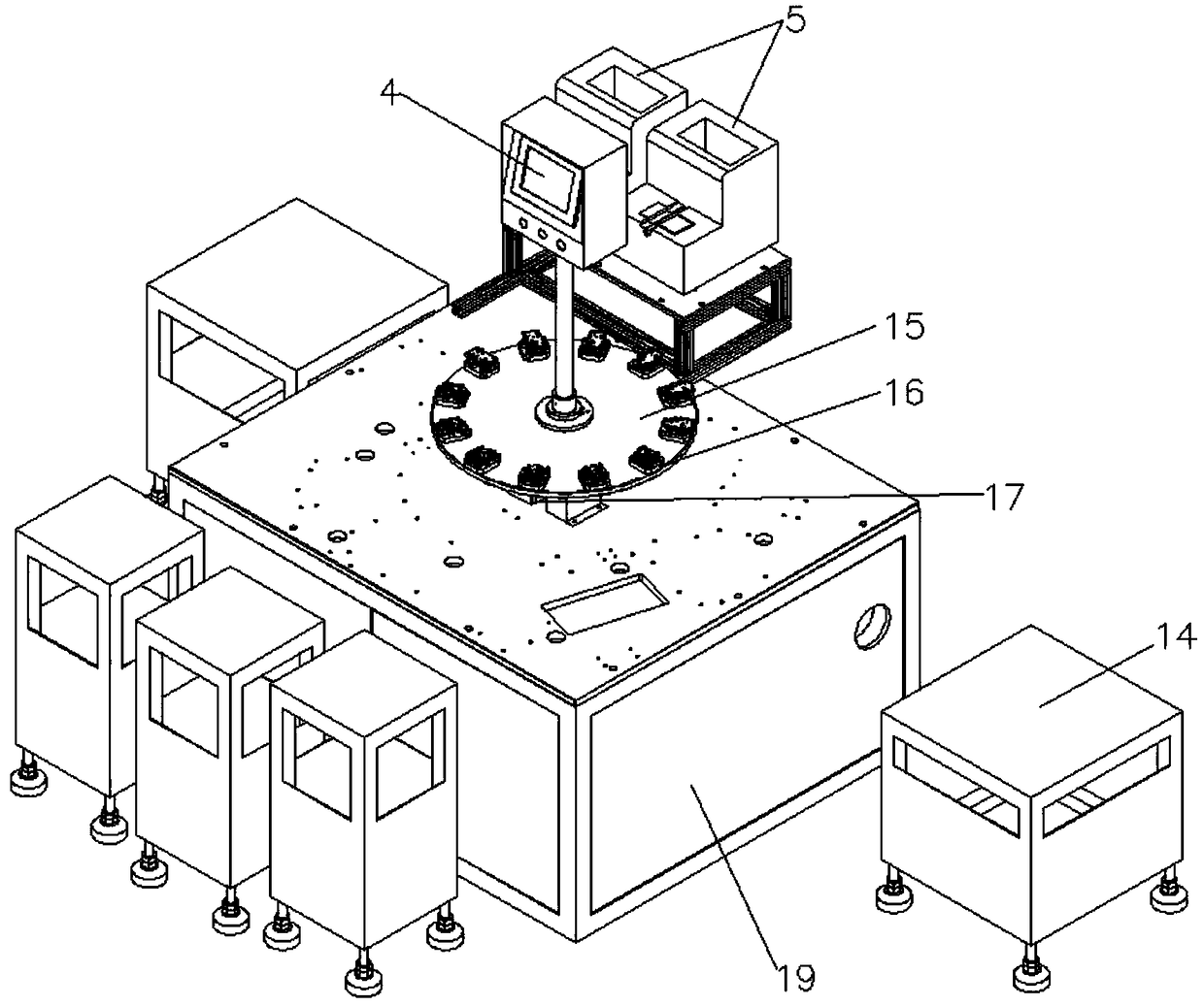
[0030] see figure 1 , figure 2 , image 3 , Figure 4 , Figure 5 , Image 6 , Figure 7 , Figure 8 , Figure 9 , Figure 10 , Figure 11 , Figure 12 , Figure 13 , Figure 14 , Figure 15 , Figure 16 with Figure 17 , the present invention provides a technical solution: an electric wave box automatic assembly machine with variable direction locking screws, including an oil point mechanism 1, an upper cover mechanism 2, an upper cover preloa...
PUM
Abstract
The invention discloses an electric gearbox automatic assembly machine capable of turning to lock a screw. The electric gearbox automatic assembly machine comprises an oiling mechanism, an upper covertaking mechanism, an upper cover pre-presser, a touch-control screen, a screw array, a screw locking mechanism, a discharge inspector, a lower cover taking mechanism, a gear B taking mechanism, a gear A taking mechanism, a turbine taking structure, a motor conveying mechanism, a lower cover detector, a table rack and a rack, wherein the upper cover taking mechanism is mounted at one side of the rack; the lower cover taking mechanism is mounted at the other side of the rack; the table rack is arranged on the bottom of each of the upper cover taking mechanism, the lower cover taking mechanism,the gear B taking mechanism, the gear A taking mechanism and the turbine taking structure; a full-material stop device is arranged at a conveying material path of the machine; the full-material stop device adopts a correlation type; after the material conveying path is full, a vibrating disc is controlled to stop supplying materials, so that electric energy is saved, noises are reduced, and resonance possibility is reduced; and meanwhile, the materials are prevented from being extruded out of the material path as a result of too great extrusion force, so that production cost is reduced.
Description
technical field [0001] The invention belongs to the technical field of assembly machines, and in particular relates to an automatic assembly machine for electric wave boxes with variable direction lock screws. Background technique [0002] Automatic assembly machine is a highly automated assembly machine that is widely used in various packaging industries and electronic product assembly industries. In layman's terms, assembly refers to the combination of several parts of the product through tight fit, buckle, screw connection, bonding, riveting, welding, etc. to obtain a finished product (semi-finished product) that meets the predetermined dimensional accuracy and function. Strictly speaking, the assembly realized by manual processing (touching, sorting, grasping, moving, placing, applying force, etc.) of each component can only be called manual assembly. Assembly that does not require manual handling (touching, sorting, grabbing, moving, placing, etc.) of parts can be call...
Claims
Application Information
Patent Timeline
Application Date:The date an application was filed.
Publication Date:The date a patent or application was officially published.
First Publication Date:The earliest publication date of a patent with the same application number.
Issue Date:Publication date of the patent grant document.
PCT Entry Date:The Entry date of PCT National Phase.
Estimated Expiry Date:The statutory expiry date of a patent right according to the Patent Law, and it is the longest term of protection that the patent right can achieve without the termination of the patent right due to other reasons(Term extension factor has been taken into account ).
Invalid Date:Actual expiry date is based on effective date or publication date of legal transaction data of invalid patent.