Control method and device for joint speed reducer of joint robot

A technology of a control device and a control method, applied in the direction of program control manipulators, manipulators, manufacturing tools, etc., can solve problems such as the inability to adapt to the requirements of automation equipment intelligence and informatization, the difficulty of popularizing and applying high-precision robots, and the inability to achieve high-precision positioning. , to achieve the effect of remote information monitoring, novel design method and low cost

Active Publication Date: 2018-10-16
黄云汉
View PDF6 Cites 0 Cited by
  • Summary
  • Abstract
  • Description
  • Claims
  • Application Information

AI Technical Summary

Problems solved by technology

[0003] ①The cost of high-precision reducers is very high, which directly leads to the high price of articulated robots, and indirectly makes it difficult for high-precision robots to be widely used in small and micro manufacturing enterprises
[0004] ② This method requires the reducer to have sufficient accuracy and a very small transmission gap, but when the reducer is worn out, the accuracy will be lost, resulting in the inability to achieve the purpose of high-precision positioning
[0005] ③This method cannot be controlled and adjusted according to the actual situation in the application process. Therefore, not only cannot it meet the future intelligent and information requirements for automation equipment, but it is also easy to replace, update and upgrade the mechanical parts, and change the tooling. produce positioning deviation or even error

Method used


Image

  • Control method and device for joint speed reducer of joint robot

Examples


Embodiment Construction

[0017] The following will clearly and completely describe the technical solutions in the embodiments of the present invention with reference to the accompanying drawings in the embodiments of the present invention. Obviously, the described embodiments are only some, not all, embodiments of the present invention. Based on the embodiments of the present invention, all other embodiments obtained by persons of ordinary skill in the art without making creative efforts belong to the protection scope of the present invention.

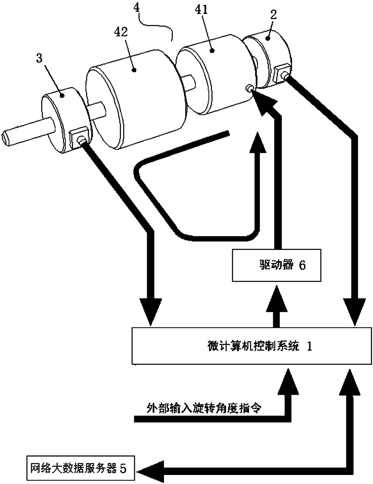
[0018] An embodiment of the present invention provides a control method for a joint reducer of an articulated robot, including:

[0019] Step 1, collecting displacement data of the input end and output end of the reduction mechanism in real time;

[0020] Step 2. Analyze the displacement data of the input end and the output end of the reduction mechanism in real time to obtain the current transmission ratio data of the reduction mechanism, the current transmis...


PUM


Abstract

The invention relates to a control method and device for a joint speed reducer of a joint robot. The control method comprises the steps that displacement data of the input end and the output end of aspeed reduction mechanism are collected in real time; the displacement data of the input end and the output end of the speed reduction mechanism are analyzed in real time, and accordingly current transmission ratio data and current transmission gap data of the speed reduction mechanism and abrasion loss data of the speed reduction mechanism are obtained; and according to the current transmission ratio and the current transmission gap data of the speed reduction mechanism and the abrasion loss data of the speed reduction mechanism, the drive power of the speed reduction mechanism is adjusted, and accordingly the drive power of the speed reduction mechanism adapts to the current work state of the speed reduction mechanism. According to the control method and device for the joint speed reducer of the joint robot, usage of a high-cost speed reducer can be avoided, real-time accurate control over the speed reducer can be achieved, and accordingly high-stability and high-precision positioning of the speed reducer is kept.

Description

technical field [0001] The invention relates to the field of electromechanical technology, in particular to a control method and device for a joint reducer of an articulated robot. Background technique [0002] In the prior art, high-precision reducers such as harmonic reducers or RV reducers are driven by power actuators such as servo motors or stepping motors to achieve high-precision positioning of the joints of articulated robots. The reduction ratio needs to be preset as a constant in the driver of the articulated robot. Although this method can achieve the technical purpose of high-precision positioning to a certain extent, it has the following disadvantages: [0003] ①The cost of high-precision reducers is very high, which directly leads to the high price of articulated robots, and indirectly makes it difficult for high-precision robots to be widely used in small and micro manufacturing enterprises. [0004] ② This method requires the reducer to have sufficient prec...

Claims


Application Information

Patent Timeline
Patent Type & Authority Applications(China)
IPC IPC(8): B25J9/16B25J13/08
CPCB25J9/1669B25J13/08
Inventor 黄云汉
Owner 黄云汉
Why Eureka
Try Eureka