Energy-saving multi-purpose printing and dyeing machine

A printing and dyeing machine and multi-purpose technology, applied in the field of printing and dyeing machines, can solve the problems of inability to fine-tune, affect the adaptability of cloth and the quality of dyed cloth, and achieve the effects of convenient and reliable adjustment, expanded gram weight range, and stable quality

Inactive Publication Date: 2018-10-16
望江硕丰汇锦科技有限公司
View PDF2 Cites 0 Cited by
  • Summary
  • Abstract
  • Description
  • Claims
  • Application Information

AI Technical Summary

Problems solved by technology

But the mesh 3 on the net cage 2 is fixed, and the water yield of the mesh circulation is certain.
The effect of controlling the pile of cloth can only be roughly determ

Method used


Image

  • Energy-saving multi-purpose printing and dyeing machine
  • Energy-saving multi-purpose printing and dyeing machine
  • Energy-saving multi-purpose printing and dyeing machine

Examples


Embodiment Construction

[0020] The specific implementation manners of the present invention will be further described in detail below in conjunction with the accompanying drawings and embodiments. The following examples are used to illustrate the present invention, but are not intended to limit the scope of the present invention.

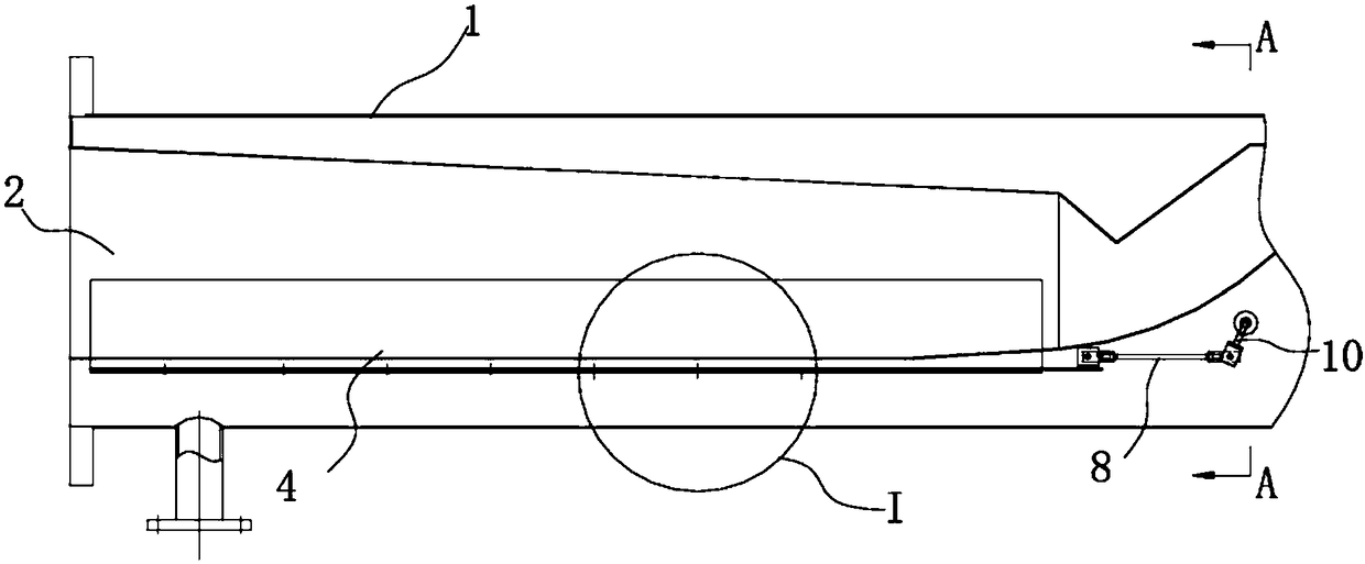
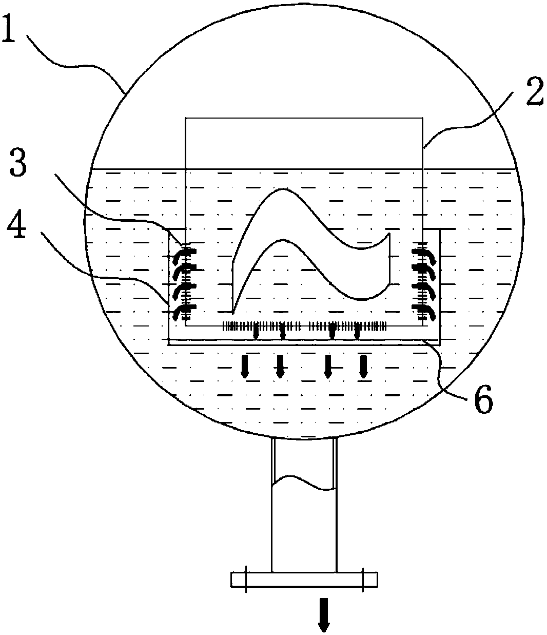
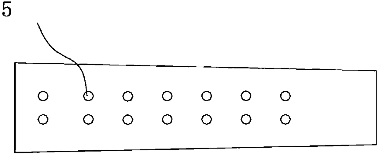
[0021] see figure 1 , figure 2 , image 3 , Figure 4 and Figure 6 As shown, the energy-saving multi-purpose printing and dyeing machine includes a net cage installed in the tail housing 1 of the printing and dyeing machine, the net cage includes a box body 2, and the box body 2 is provided with a plurality of mesh holes 3; it also includes A box cover 4 with an open upper end and a closed lower end, the box cover 4 is set outside the box body 2, the upper edge of the box cover 4 is higher than the mesh 3 and the upper edge of the box cover 4 The edge is lower than the liquid level in the tail casing 1 , and the box cover 4 is provided with a plurality of water hol...


PUM


Abstract

The invention relates to an energy-saving multi-purpose printing and dyeing machine capable of controlling the amount of water flowing through mesh holes and further fine-adjusting to control the effect cloth piling so as to better improve the quality of the dyed cloth. The machine comprises a net cage installed in a tail casing of the printing and dyeing machine, the net cage comprises a cage body, wherein the cage body is provided with a plurality of mesh holes; the machine also comprises a cage body sleeve with an opening upper end and a closed lower end, the cage body sleeve sleeves outside the cage body, the upper edge of the cage body sleeve is higher than the mesh holes, and the upper edge of the cage body sleeve is lower than the liquid level in the tail shell, a plurality of waterpassing holes are arranged on the cage body sleeve, a water passing adjustment device is arranged on the cage body sleeve.

Description

technical field [0001] The invention relates to a printing and dyeing machine. Background technique [0002] The weight of cloth (thickness of cloth) is different, and different high-temperature and high-pressure printing and dyeing machines are required, and the output of dyed cloth varies with market changes. This requires a more low-carbon, environmentally friendly, and versatile printing and dyeing machine. Such as Figure 9 As shown, the existing printing and dyeing machine is equipped with a net cage 2 in the tail housing of the dyeing machine, which controls the placement of the cloth during cloth printing and dyeing, and roughly controls the walking speed and speed of the cloth by controlling the size of the suction port under the net cage 2. Sort of cloth. But the mesh 3 on the net cage 2 is fixed, and the water yield of mesh circulation is certain. The effect of controlling the pile of cloth can only be roughly determined by the size of the water suction port, a...

Claims


Application Information

Patent Timeline
IPC IPC(8): D06B23/04
CPCD06B23/042
Inventor 曹结渝
Owner 望江硕丰汇锦科技有限公司
Why Eureka
Try Eureka