Eureka AIR delivers breakthrough ideas for toughest innovation challenges, trusted by R&D personnel around the world.

Engine intake valve continuous variable system and engine

An engine and intake valve technology, applied in engine components, machines/engines, mechanical equipment, etc., can solve problems such as low flexibility in valve adjustment and complex structure, to overcome consistency differences and reliability problems, and reduce energy. consumption and cost reduction

Active Publication Date: 2018-10-16
WEICHAI POWER CO LTD
View PDF5 Cites 3 Cited by
  • Summary
  • Abstract
  • Description
  • Claims
  • Application Information

AI Technical Summary

Problems solved by technology

[0003] At present, the existing variable valve drive mechanism mainly uses changing the cam phase, but the structure is relatively complicated, and the original engine has been changed a lot. It is more common in low-power gasoline engines, and it is rarely used in high-power diesel engines, especially for side bottoms. The intake and exhaust valves of a cam engine are driven by the same cam, so it is difficult to adjust the intake and exhaust valves separately, and most of the existing variable valve products of diesel engine oil are variable in two stages, and the flexibility of valve adjustment is not high

Method used


Image

  • Engine intake valve continuous variable system and engine
  • Engine intake valve continuous variable system and engine

Examples


Embodiment Construction

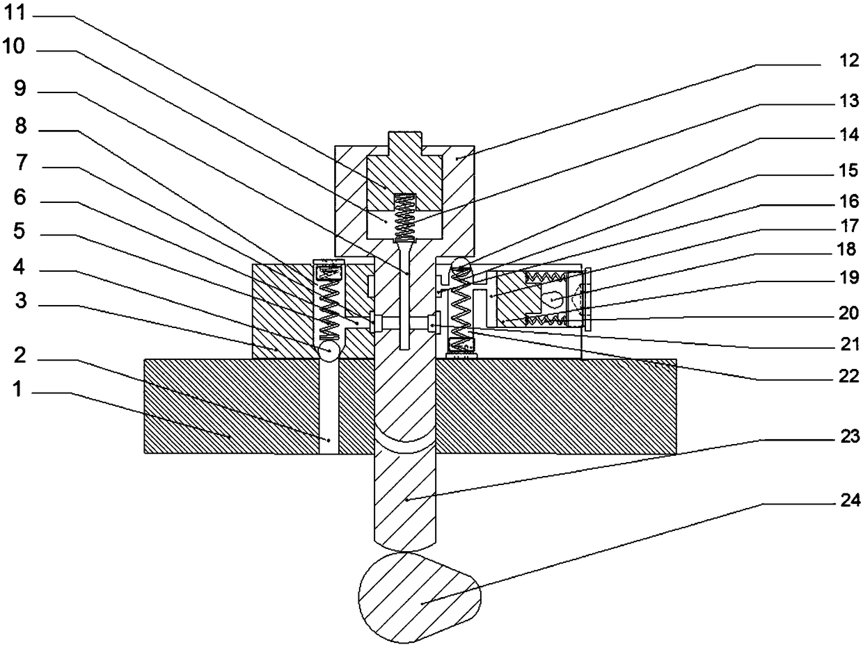
[0029] The first object of the present invention is to provide a continuously variable engine intake valve system, the structural design of which can make the engine intake valve continuously variable system simple in structure, high in reliability and flexible in use; the second aspect of the present invention One object is to provide an engine including the above continuously variable intake valve system of the engine.

[0030] The following will clearly and completely describe the technical solutions in the embodiments of the present invention with reference to the accompanying drawings in the embodiments of the present invention. Obviously, the described embodiments are only some, not all, embodiments of the present invention. Based on the embodiments of the present invention, all other embodiments obtained by persons of ordinary skill in the art without making creative efforts belong to the protection scope of the present invention.

[0031] see figure 1 , figure 1 A sc...


PUM


Abstract

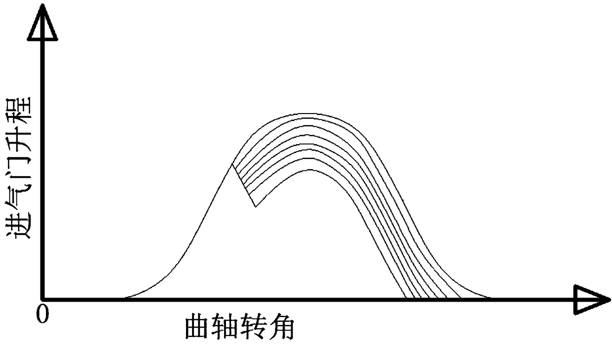
The invention discloses an engine intake valve continuous variable system and an engine. The intake valve continuous variable system comprises a base and a tappet rod, wherein the tappet rod is arranged on the base in a sliding mode; the tappet rod comprises a push rod and a valve core, the valve core is provided with a first pressure chamber, a first plunger is arranged in the first pressure chamber, and a push rod oil inlet channel is in communication with the first pressure chamber; a one-way valve is arranged in a base communication oil channel, an oil drainage channel is in communicationwith an oil inlet channel and the second pressure chamber, a second plunger is arranged in the second pressure chamber, an adjustable limiting device for adjusting the maximum displacement of the second plunger is arranged in the second pressure chamber, and the second plunger abuts against the side wall of the second pressure chamber under the action of a reset piece; and an oil drainage valve isarranged in an oil drainage hole of the oil drainage channel, and the oil drainage valve is opened when the oil drainage valve is in contact with the bottom of the valve core. According to the intakevalve continuous variable system, a mechanical structure is adopted, the oil supply is completed by utilizing the engine oil pressure of the engine lubricating oil path, the robustness and the reliability of the system are guaranteed, the cost and the energy consumption are reduced, the continuous adjustment of the closing timing of the multi-cylinder intake valve can be realized, and the performance of the engine is improved.

Description

technical field [0001] The invention relates to the technical field of engines, in particular to an engine intake valve continuously variable system and an engine. Background technique [0002] Traditional four-stroke engines generally use mechanical cams to drive the valve trains of the intake and exhaust valves. The valve movement is controlled by the mechanical transmission between the cam and each valve. This mechanical mechanism is simple and reliable, but the parameters such as the opening time and phase of the valve mechanism are fixed, and the performance of the engine cannot be fully utilized. The variable gas distribution technology can make the valve timing provide variable valve opening and closing time or lift under different engine speeds and loads, thereby improving engine intake and exhaust performance, and better meeting the needs of the engine at high speeds and loads. Due to the power, economy and emission requirements at low speed, high load and low load...

Claims


Application Information

Patent Timeline
Patent Type & Authority Applications(China)
IPC IPC(8): F01L1/344F01L13/00
CPCF01L1/3442F01L13/0031F01L2001/34426
Inventor 战强李志强朱纪宾
Owner WEICHAI POWER CO LTD
Why Eureka
Eureka Blog
Learn More