Display apparatus

一种显示装置、图像光的技术,应用在光导、光学、仪器等方向,能够解决未公开、未公开制造等问题

Active Publication Date: 2018-10-16
SEIKO EPSON CORP
View PDF10 Cites 1 Cited by
  • Summary
  • Abstract
  • Description
  • Claims
  • Application Information

AI Technical Summary

Problems solved by technology

However, there is no structure disclosed in Patent Documents 1, 2 for satisfying the above-mentioned requirements at the same time.
In addition, although Patent Document 2 describes a structure in which a light guide system is formed by joining two translucent members, it does not disclose how to manufacture a translucent member having a plurality of partially reflective surfaces at low cost. Techniques suitable for jointed structures

Method used


Image

  • Display apparatus
  • Display apparatus
  • Display apparatus

Examples


Embodiment approach 1

[0043] (the whole frame)

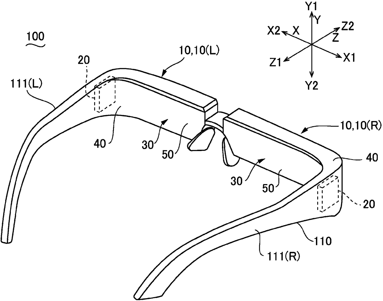
[0044] figure 1 It is an explanatory diagram schematically showing an example of the appearance of the display device 100 according to Embodiment 1 of the present invention. figure 1 The shown display device 100 is configured as a see-through eyewear display or the like, and has a frame 110 including temples 111 (R) and 111 (L) on the left and right. A display unit 10 , which will be described later, of the display device 100 is supported by a frame 110 , and allows the user to recognize an image emitted from the display unit 10 as a virtual image. In the present embodiment, the display device 100 includes a display unit 10 (R) for the right eye and a display unit 10 (L) for the left eye as the display unit 10 . The display unit 10 (R) for the right eye and the display unit 10 (L) for the left eye have the same configuration and are arranged bilaterally symmetrically. Therefore, in the following description, the display unit 10 (R) for the right e...

Embodiment approach 2

[0086] Figure 7 It is a plan view of the optical system of the display device 100 according to Embodiment 2 of the present invention. In addition, since the basic structure of this form and each embodiment mentioned later is the same as that of Embodiment 1, the same code|symbol is attached|subjected to a common part, and their description is abbreviate|omitted.

[0087] Such as Figure 7 As shown, in this embodiment, as in Embodiment 1, the incident portion 40 is formed by the first translucent member 61, and the portion 54 of the light guide portion 50 on which at least a plurality of partial reflection surfaces 55 are formed is formed by the second The translucent member 62 is formed, and the second translucent member 62 is surface-bonded to the first translucent member 61 in the first direction X via the bonding surface 63 (first bonding surface). In this embodiment, the bonding surface 63 is arranged between the plurality of partial reflection surfaces 55 and the one e...

Embodiment approach 3

[0089] Figure 8 It is a plan view of the optical system of the display device 100 according to Embodiment 3 of the present invention. Such as Figure 8 As shown, in this embodiment, as in Embodiment 1, the incident part 40 is formed by the first translucent member 61, and the part 54 of the light guide part 50 where at least a plurality of partial reflection surfaces 55 are formed is formed by the second translucent member 61. The optical member 62 is formed, and this 2nd translucent member 62 is surface-bonded with the 1st translucent member 61 in the 1st direction X via the bonding surface 63 (1st bonding surface). In the present embodiment, the bonding surface 63 is positioned to overlap the partial reflection surface 55 located on the side of the most end 51 among the plurality of partial reflection surfaces 55 . Therefore, as in the first embodiment, the bonding surface 63 is inclined in the same direction as the partial reflection surface 55 . The other structures ar...


PUM


Abstract

Provided is a display apparatus, and even though a light guide portion is very thin, image light beams in high brightness can be emitted from a light-emitting portion, and a transparent member which has a plurality of partial reflection layers can be manufactured to a structure that is suitable for joining in low cost. A light guide system (30) that includes a light-incident portion (40) includinga light-incident curved surface (41) on which image light beams (L) as non-parallel light beams (L) are incident and a light-reflective curved surface (42) which reflects the image light beams (L) such that the image light beams (L) are converted into parallel light beams, and a light guide portion (50) being a portion in which a plurality of partial reflection layers (55) are disposed in parallel. The light guide portion (50) is filled with a parallel light flux emitted from the light-incident portion (40). The light-incident portion (40) is formed of a first transparent member (61), the portion (54) in which the partial reflection layers (55) are formed is formed of a second transparent member (62) which is surface-bonded to the first transparent member (61) via a bonding surface (63),and the bonding surface (63) is inclined in the same direction as that of the partial reflection layer (55).

Description

technical field [0001] The present invention relates to a display device equipped with a light guide system. Background technique [0002] As a display device, there has been proposed a configuration including a light guide system in which a light guide extends from an incident part where image light enters, and image light incident from the incident part is guided to an emission part through the light guide (see Patent Document 1). The incident part is formed with an incident curved surface and a reflective curved surface. After the image light enters from the incident curved surface, it is reflected between the reflective curved surface and the incident curved surface and is guided to the light guide part. On the other hand, a light guide system in which a plurality of partial reflection surfaces and a light guide part are arranged parallel to each other has been proposed, and a part in which a plurality of partial reflection surfaces are formed and an incident part in whi...

Claims


Application Information

Patent Timeline
Patent Type & Authority Applications(China)
IPC IPC(8): G02B27/01G02B6/10
CPCG02B6/10G02B27/0172G02B2027/0178G02B5/10G02B6/0028G02B27/1066G02B2027/0123G02B6/0055G02B27/0176G02B2027/0136
Inventor 松木隼人武田高司
Owner SEIKO EPSON CORP
Why Eureka
Try Eureka