Efficient double-shaft shredder for use in paint bucket

A double-shaft shredder and paint bucket technology, applied in grain processing, etc., can solve the problems of inconvenience, single structure of the feed box, and reduce labor force, and achieve the effects of increasing stability, increasing shredding efficiency, and increasing work efficiency

Inactive Publication Date: 2018-10-19
ZHEJIANG COLLEGE OF ZHEJIANG UNIV OF TECHOLOGY
View PDF0 Cites 0 Cited by
  • Summary
  • Abstract
  • Description
  • Claims
  • Application Information

AI Technical Summary

Problems solved by technology

[0003] At present, paint buckets are usually shredded by a double-shaft shredder in the market. The existing double-shaft shredder mainly consists of a support base, a shredding box, a transmission mechanism, a shredding mechanism and a feeding Usually, the paint bucket is put into the shredder box through the feed box for shredding. Since the existing feed box structure is relatively simple, when the cylindrical paint bucket is shredded, if the paint bucket is placed horizontally When inside the shredding box, the shredding mechanism can’t shred the paint bucket well. It is necessary to manually place the paint bucket vertically on the shredding mechanism to better shred the paint bucket, which is extremely inconvenient. It is necessary to improve the structure of the feed box of the double-shaft shredder to increase the shredding efficiency of the paint bucket and reduce the labor force

Method used


Image

  • Efficient double-shaft shredder for use in paint bucket
  • Efficient double-shaft shredder for use in paint bucket
  • Efficient double-shaft shredder for use in paint bucket

Examples


Embodiment Construction

[0021] The following will clearly and completely describe the technical solutions in the embodiments of the present invention with reference to the accompanying drawings in the embodiments of the present invention. Obviously, the described embodiments are only some, not all, embodiments of the present invention. Based on the embodiments of the present invention, all other embodiments obtained by persons of ordinary skill in the art without making creative efforts belong to the protection scope of the present invention.

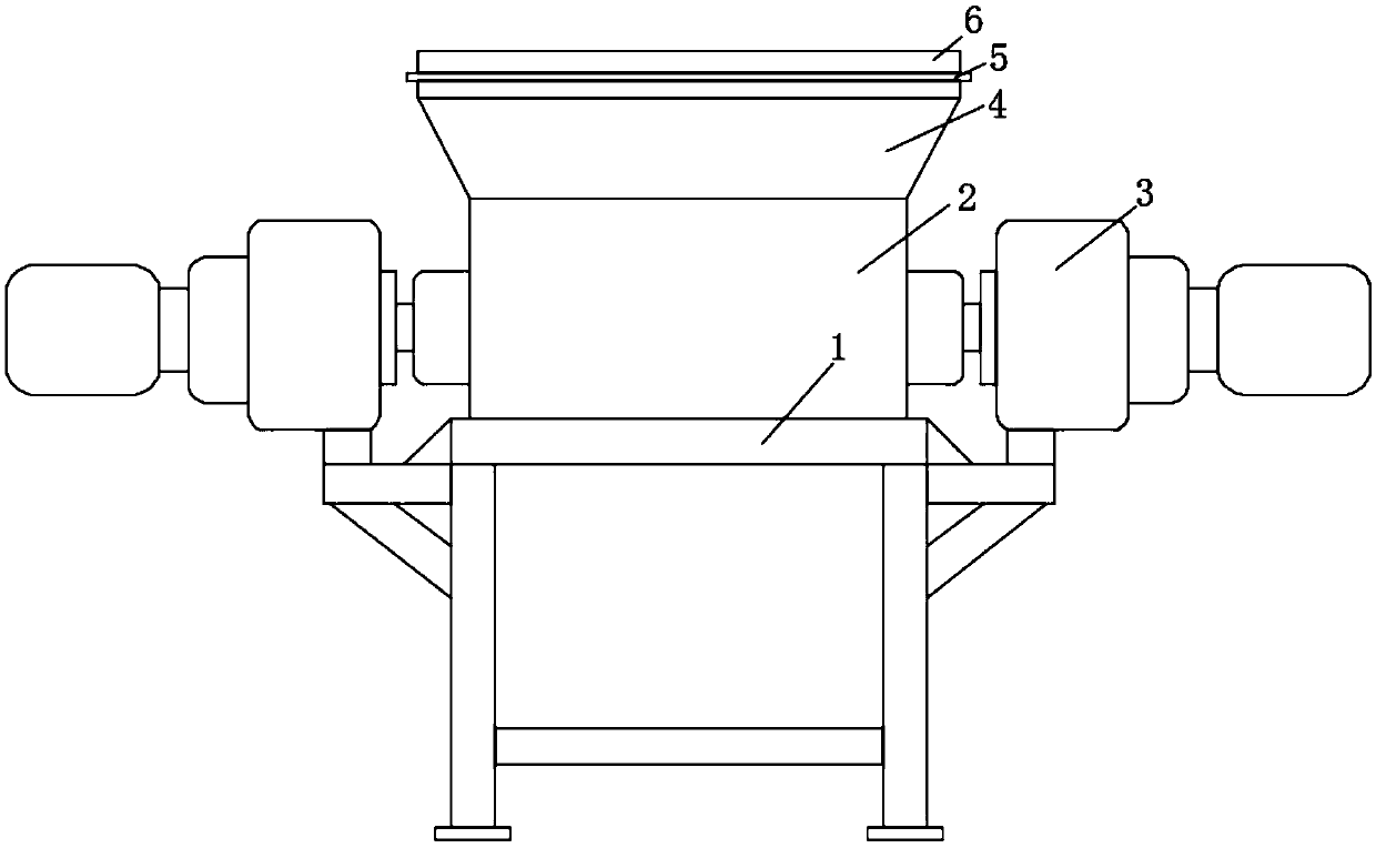
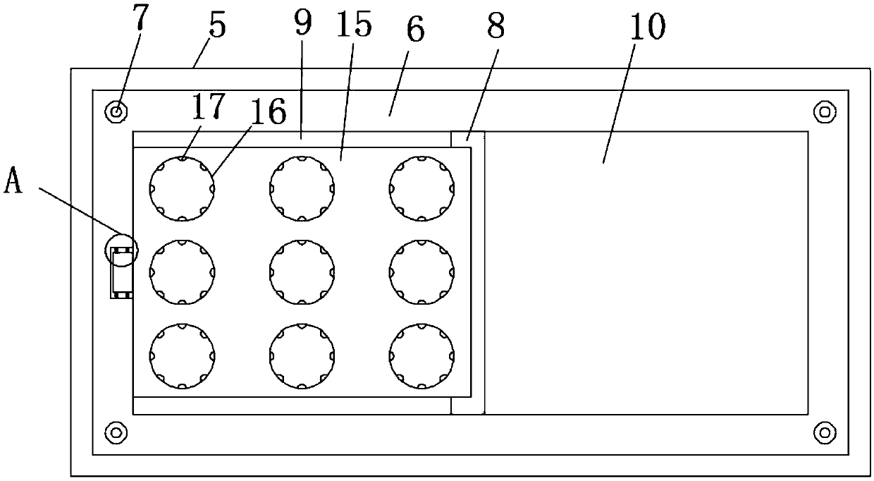
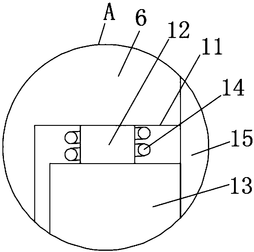
[0022] see Figure 1-4 , the present invention provides a technical solution: a high-efficiency biaxial shredder for paint buckets, including a support base 1, a shredding box 2 is fixedly installed above the support base 1, and the inside of the shredding box 2 is provided with Shredding mechanism, both sides of the shredding box 2 are equipped with a transmission mechanism 3, and the transmission mechanism 3 is connected with the shredding mechanism, the top...


PUM


Abstract

The invention discloses an efficient double-shaft shredder for use in a paint bucket, the efficient double-shaft shredder comprises a support base, a tear box is fixedly mounted above the support base, a partition plate is fixedly mounted in the middle portion of a positioning frame, thereby facilitating to divide the positioning frame into a first feeding port and a second feeding port, so that classified shredding can be performed in the paint bucket, work efficiency is increased, a rotating shaft is movably connected in a cavity arranged on the left upper surface of the positioning frame tofacilitate flip-flop movement on the rotating shaft of a limiting plate by a connecting block, a feeding limiting hole is arranged on the surface of the limiting plate, a bull's eye bearing is installed inside the feeding limiting hole, so that a material can be guided, fed and limited into the paint bucket, a magnet II is fixedly mounted inside a limiting slot, the limiting plate is attracted tothe magnet II by a magnet I, the limiting plate can be better adsorbed on the partition plate, so that the position of the limiting plate is not easily biased, and the feeding stability is increased.

Description

technical field [0001] The invention relates to the technical field of twin-shaft shredders, in particular to a high-efficiency twin-shaft shredder used for paint buckets. Background technique [0002] In recent years, the economy of the Yangtze River Delta region has grown rapidly, and the scale of industrial production has continued to expand. The industrial economy accounts for more than 40% of the country's total. Economic development, especially the development of advanced equipment manufacturing, has become the main industry of this region's industrial economy. Waste paint bucket is a kind of industrial and civil common solid waste. Waste paint buckets contain a lot of toxic substances. If discarded at will, corrupt waste paint buckets will destroy our water sources, erode the crops and land we depend on for survival, and our living environment will face a huge threat. [0003] At present, paint buckets are usually shredded by a double-shaft shredder in the market. T...

Claims


Application Information

Patent Timeline
Patent Type & Authority Applications(China)
IPC IPC(8): B02C18/22
CPCB02C18/2225B02C18/0092B02C2201/06
Inventor 赵正平潘宸宇钟明强蒋国军
Owner ZHEJIANG COLLEGE OF ZHEJIANG UNIV OF TECHOLOGY
Why Eureka
Try Eureka