Mineral separation washbox

A jig and box technology, applied in the field of beneficiation jigs, can solve problems such as low separation rate and complex structure of reciprocating drive device

Inactive Publication Date: 2018-10-19
江西金石宝矿山机械制造有限公司
View PDF0 Cites 4 Cited by
  • Summary
  • Abstract
  • Description
  • Claims
  • Application Information

AI Technical Summary

Problems solved by technology

The disadvantage of the jig with this structure is that the structure of the reciprocating drive device is complex, and the drive of the double-cone bucket is synchronous, and the selection rate is low.

Method used


Image

  • Mineral separation washbox
  • Mineral separation washbox

Examples


Embodiment Construction

[0012] The following will clearly and completely describe the technical solutions in the embodiments of the present invention with reference to the accompanying drawings in the embodiments of the present invention. Obviously, the described embodiments are only some, not all, embodiments of the present invention. Based on the embodiments of the present invention, all other embodiments obtained by persons of ordinary skill in the art without making creative efforts belong to the protection scope of the present invention.

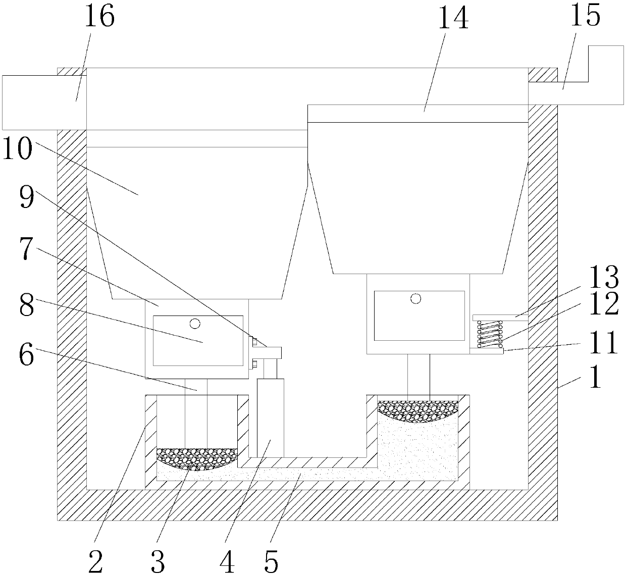
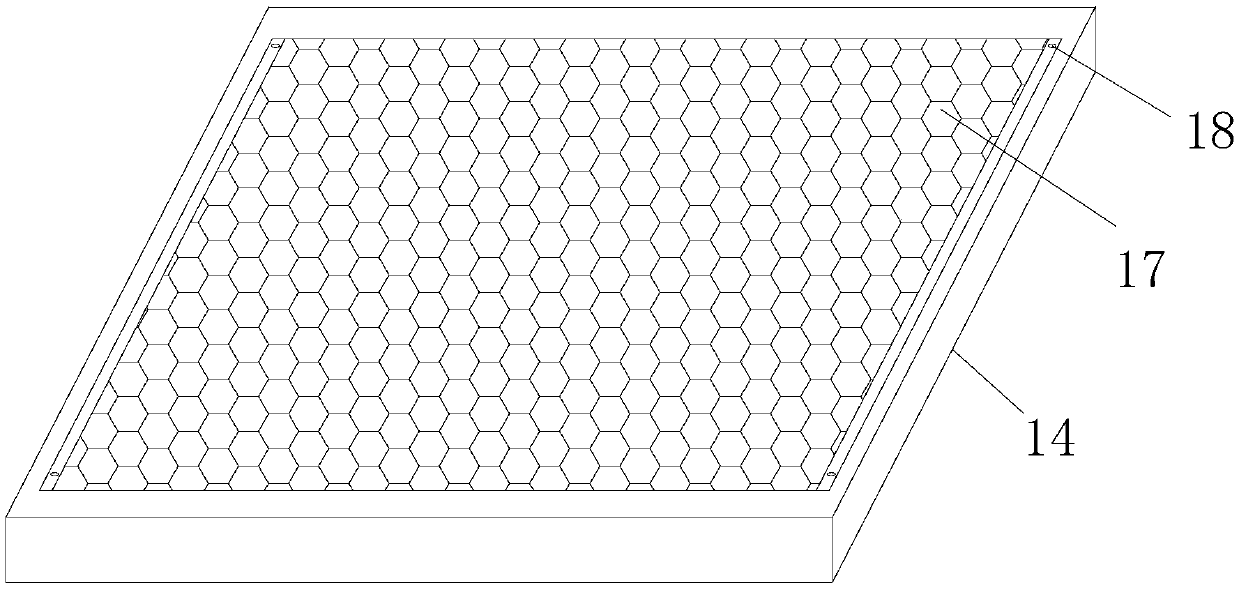
[0013] see Figure 1-2 , the present invention provides a technical solution: a mineral processing jig, including a box body 1, a U-shaped tube 2 is provided on the inner bottom wall of the box body 1, and pistons are slidably connected inside the nozzles at both ends of the U-shaped tube 2 3. The inside of the U-shaped tube 2 is filled with hydraulic oil 5, and the hydraulic rod 4 is installed on the U-shaped tube 2. The top surface of the piston 3 is fixedly...


PUM


Abstract

The invention discloses a mineral separation washbox. The mineral separation washbox comprises a box body, a U-shaped pipe is arranged on the bottom wall of the interior of the box body, pistons are in sliding connection into interiors of pipe openings in the two ends of the U-shaped pipe, the interior of the U-shaped pipe is filled with hydraulic oil, a hydraulic rod is arranged on the U-shaped pipe, the top end face of the piston is fixedly connected with the bottom end of a supporting rod, the top end of the supporting rod is fixedly connected with a discharging box, the top of the discharging box is in through connection with a feeding box, the front side wall of the discharging box is movably provided with a push-pull type drawer, the position, close to the left side wall of the interior of the box body, of the right side wall of the discharging box is fixedly connected with one end of a partition board, the top end of the piston rod of the hydraulic rod is fixedly connected withthe center of the bottom end face of the partition board, the position, close to the right side wall of the interior of the box body, of the right side wall of the discharging box is fixedly connectedwith one end of a first baffle, a second baffle is fixedly welded to the right side wall of the interior of the box body, and a spring is fixedly connected between the first baffle and the second baffle. The mineral separation washbox is compact in structure and convenient to use.

Description

technical field [0001] The invention relates to the field of jig equipment, in particular to an ore dressing jig. Background technique [0002] At present, the jig used for mineral separation includes a frame body, a box body is arranged on the frame body, a feeding port and an overflow port are arranged on the box body, and a sieve plate is arranged in the middle of the box body. Two diaphragms are connected to the lower part of the box body, and two cone buckets are connected to the lower part of the two diaphragms. There is a grit chamber at the bottom of the two cone buckets. The cone bucket reciprocates up and down, so that the water in the tank flows up and down alternately. The minerals with high density and smaller than the size of the sieve hole pass through the sieve plate and enter the cone bucket to be discharged from the sand outlet. orifice discharge. The disadvantage of the jig with this structure is that the structure of the reciprocating drive device is co...

Claims


Application Information

Patent Timeline
Patent Type & Authority Applications(China)
IPC IPC(8): B03B5/16B03B5/24
CPCB03B5/16B03B5/24
Inventor 黄佩
Owner 江西金石宝矿山机械制造有限公司
Why Eureka
Try Eureka