Cutting machine capable of automatically switching sawblade
A technology for automatic switching and cutting machines, applied in the direction of sawing machine, metal sawing equipment, metal processing equipment, etc., can solve the problems of saw blade damage, operator danger, etc., and achieve the effect of preventing damage
- Summary
- Abstract
- Description
- Claims
- Application Information
AI Technical Summary
Problems solved by technology
Method used
Image

Examples
Embodiment Construction
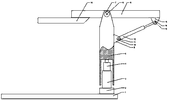
[0021] The present invention is specifically described below in conjunction with accompanying drawing, as Figure 1-5 As shown, a cutting machine that can automatically switch saw blades includes a base 1, the base 1 is located above the ground, and a saw arm mechanism is respectively arranged above the base 1, and the saw arm mechanism is fixedly connected by a The saw arm base 2, the saw arm heightening linear motor mounting frame 3 fixedly connected above the saw arm base 2, the saw arm heightening linear motor 4 installed on the saw arm heightening linear motor mounting frame 3, the saw arm heightening linear motor 4 The saw arm heightening frame 5 fixedly connected to the telescopic end, the saw arm heightening frame bearing 6 installed on one end of the saw arm heightening frame 5, the saw arm rotating arm shaft 7 inserted on the saw arm heightening frame bearing 6, and the saw arm rotating arm The saw arm rotating arm 8 fixedly connected to the shaft 7, the rotating arm...
PUM
 Abstract
Description
Claims
Application Information
PatSnap Eureka turns technology decisions into work you can execute. Powered by our Innovation Knowledge Graph, it runs expert workflows across engineering, life sciences, materials and intellectual property. Get your review-ready output in minutes.


