
Cutting apparatus for bearing pedestal cutting

A technology of cutting device and bearing seat, applied in the field of bearing seat, can solve the problems of time-consuming and laborious cutting, slow production efficiency, etc., and achieve the effects of avoiding excessive temperature, improving production efficiency, and avoiding environmental pollution

Inactive Publication Date: 2018-10-19
响水星火传动件有限公司
View PDF0 Cites 4 Cited by
  • Summary
  • Abstract
  • Description
  • Claims
  • Application Information

AI Technical Summary

Problems solved by technology

[0004] The purpose of the present invention is to solve the problem that the cutting of rough metal is mostly manual cutting in the prior art, which is not only time-consuming and labor-intensive, but also the production efficiency is slow and the temperature is low, and a cutting device for bearing seat blanking is proposed.

Method used


Image

  • Cutting apparatus for bearing pedestal cutting
  • Cutting apparatus for bearing pedestal cutting

Examples


Embodiment Construction

[0018] The following will clearly and completely describe the technical solutions in the embodiments of the present invention with reference to the accompanying drawings in the embodiments of the present invention. Obviously, the described embodiments are only some, not all, embodiments of the present invention.

[0019] In describing the present invention, it should be understood that the terms "upper", "lower", "front", "rear", "left", "right", "top", "bottom", "inner", " The orientation or positional relationship indicated by "outside", etc. is based on the orientation or positional relationship shown in the drawings, and is only for the convenience of describing the present invention and simplifying the description, rather than indicating or implying that the referred device or element must have a specific orientation, so as to Specific orientation configurations and operations, therefore, are not to be construed as limitations on the invention.

[0020] refer to Figure ...


PUM


Abstract

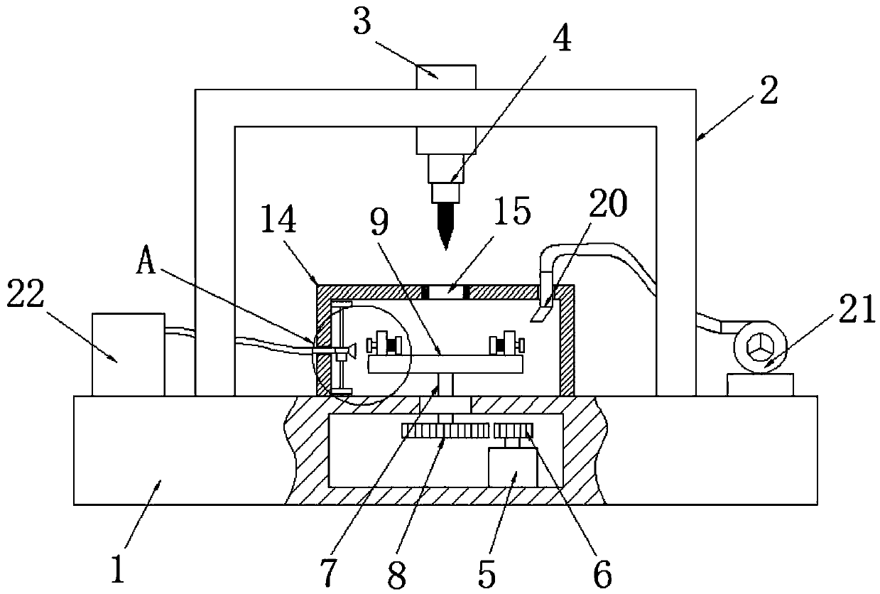
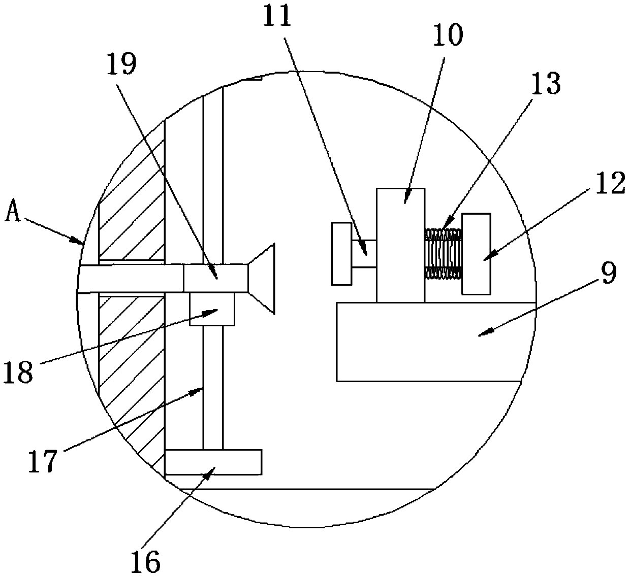
The present invention discloses a cutting apparatus for bearing pedestal cutting. The device comprises a base and a gantry arranged at an upper end of the base, wherein the upper end of the cross beamof the gantry is fixedly connected with an electric push rod through a first through hole, a lower end of the electric push rod extends into the gantry, and the lower end of the electric push rod isfixedly provided with a cutting gun; a cavity is arranged at the center of the inner part of the base, the right side of the lower end of the cavity is fixedly provided with a motor, and the output shaft of the motor is rotationally connected with a small gear; a rotating shaft is rotationally connected to the center of the upper end of the cavity through a rolling bearing, the lower end of the rotating shaft is fixedly provided with a large gear, the large gear and the small gear are meshed; the upper end of the rotating shaft penetrates through the rolling bearing and extends outwards, and the upper end of the rotating shaft is fixedly provided with a rotating disc. According to the cutting apparatus for bearing pedestal cutting, the operation is convenient, the shaft hole of the bearingpedestal can be quickly cut out, the production efficiency is improved, and the dust generated in the cutting process can be prevented from polluting the environment.

Description

technical field [0001] The invention relates to the technical field of bearing seats, in particular to a cutting device for cutting bearing seats. Background technique [0002] At present, the bearing seat needs to be processed by blanking equipment when it is produced into a finished product. First, it is necessary to cut out the corresponding shaft hole from the blank metal, and at the same time ensure the aperture of the shaft hole. [0003] In the prior art, the cutting of rough metal is mostly manual cutting, which is not only time-consuming and labor-intensive, but also slow in production efficiency. However, the CNC cutting structure is complicated, the operation is difficult, and the scope of application is limited. Therefore, the present invention has designed a kind of cutting device for bearing housing blanking. Contents of the invention [0004] The purpose of the present invention is to solve the problem of cutting rough metals manually in the prior art, whic...

Claims


Application Information

Patent Timeline
Patent Type & Authority Applications(China)
IPC IPC(8): B23D79/00
CPCB23D79/00
Inventor 于宇
Owner 响水星火传动件有限公司
Learn More