Complex adjusting mechanism for nozzle

An adjustment mechanism and nozzle technology, applied in metal processing machinery parts, maintenance and safety accessories, metal processing equipment, etc., can solve the problems of increasing the burden on workers and inconvenient adjustment of nozzles, so as to improve automatic adjustment ability, reduce labor burden, The effect of improving efficiency

Inactive Publication Date: 2018-10-19
CHONGQING HONGGANG CNC MACHINE TOOL
View PDF6 Cites 2 Cited by
  • Summary
  • Abstract
  • Description
  • Claims
  • Application Information

AI Technical Summary

Problems solved by technology

[0003] The present invention intends to provide a composite nozzle adjustment mechanism to solve the problem that the nozzles in the prior art are inconvenient to adjust, resulting in increased burden on workers

Method used


Image

  • Complex adjusting mechanism for nozzle

Examples


Embodiment Construction

[0015] The following is further described in detail through specific implementation methods:

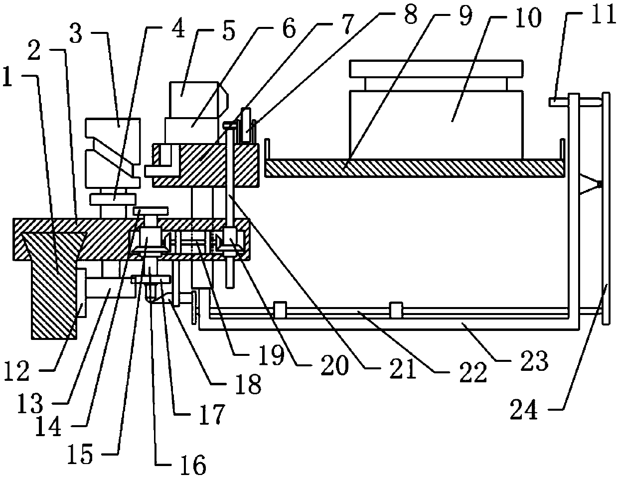
[0016] The reference signs in the drawings of the description include: guide rail 1, slider 2, cylindrical cam 3, vertical drive gear 4, nozzle 5, mounting seat 6, support block 7, wind wheel 8, material tray 9, workpiece 10, top Rod 11, rack 12, transverse drive gear 13, upper drive gear 14, second drum 15, second shaft 16, lower drive gear 17, wedge 18, drive shaft 19, first drum 20, first shaft 21, push rod 22, mobile frame 23, lever 24.

[0017] The embodiment is basically as attached figure 1 Shown: the composite nozzle adjustment mechanism, including a bracket (not shown in the figure), the bracket is provided with a horizontal adjustment assembly, the horizontal adjustment assembly includes a horizontal guide rail 1 welded on the bracket, and a rack is arranged on the guide rail 1 along the length direction 12. The rack 12 is connected to the guide rail 1 through bolts; the ...


PUM


Abstract

The invention relates to the technical field of airflow adjusting equipment, and specifically relates to a complex adjusting mechanism for a nozzle. The complex adjusting mechanism comprises a support, wherein a transverse adjusting assembly comprising a guide rail, a sliding block, a rack and a transverse driving gear is arranged on the support; a vertical adjusting assembly comprising a cylindrical cam, a supporting block, a vertical driving gear and a mounting seat is arranged on the sliding block; a transmission assembly is arranged on the sliding block; a wind wheel is driven to rotate through air in order to adjust the position of the nozzle through the transverse adjusting assembly and the vertical adjusting assembly, and thus the automatic operation is achieved. According to the scheme, the complex adjusting mechanism for the nozzle solves the problems that a nozzle in the prior art is inconveniently adjusted, and the workload of workers is increased.

Description

technical field [0001] The invention relates to the technical field of airflow adjustment equipment, in particular to a composite nozzle adjustment mechanism. Background technique [0002] When turning the workpiece, when the workpiece is processed, a material receiving device will be set up to catch the processed workpiece to facilitate unloading. When machining a cylindrical workpiece with an annular groove on its circumference, some debris will adhere to the groove. Before the workpiece enters the next processing procedure, the debris attached to the groove needs to be removed, so as to prevent the debris from affecting the processing of the workpiece in the next procedure. Existing methods for removing debris generally use air jets, so nozzles are provided on the side of the material receiving device, and the debris in the groove is blown away by the high-speed airflow ejected from the nozzles. However, since there are more than one kind of workpieces to be processed, ...

Claims


Application Information

Patent Timeline
Patent Type & Authority Applications(China)
IPC IPC(8): B23Q11/00
CPCB23Q11/005
Inventor 汪传宏
Owner CHONGQING HONGGANG CNC MACHINE TOOL
Why Eureka
Try Eureka