Yarn conveying and carding device

A yarn and mounting hole technology is applied in the field of yarn conveying and carding devices, which can solve the problems of limited working environment, potential safety hazards, and difficulty in repairing, and achieve the effect of preventing entanglement.

Inactive Publication Date: 2018-10-19
XIANGSHUI YONGTAI TEXTILE GARMENT CO LTD
View PDF0 Cites 2 Cited by
  • Summary
  • Abstract
  • Description
  • Claims
  • Application Information

AI Technical Summary

Problems solved by technology

[0002] Most of the general yarn carding equipment uses a carding plate with a fixed needle plate structure to card the yarn. The working environment is limited, fragile and difficult to repair, and there are potential safety hazards in actual use. Therefore, we need a machine that can meet various working environments. , simple in structure, easy to manufacture, safe to use and capable of good carding of yarn, the sand thread carding device meets the market demand

Method used


Image

  • Yarn conveying and carding device
  • Yarn conveying and carding device
  • Yarn conveying and carding device

Examples


Embodiment Construction

[0021] The following will clearly and completely describe the technical solutions in the embodiments of the present invention with reference to the accompanying drawings in the embodiments of the present invention. Obviously, the described embodiments are only some, not all, embodiments of the present invention.

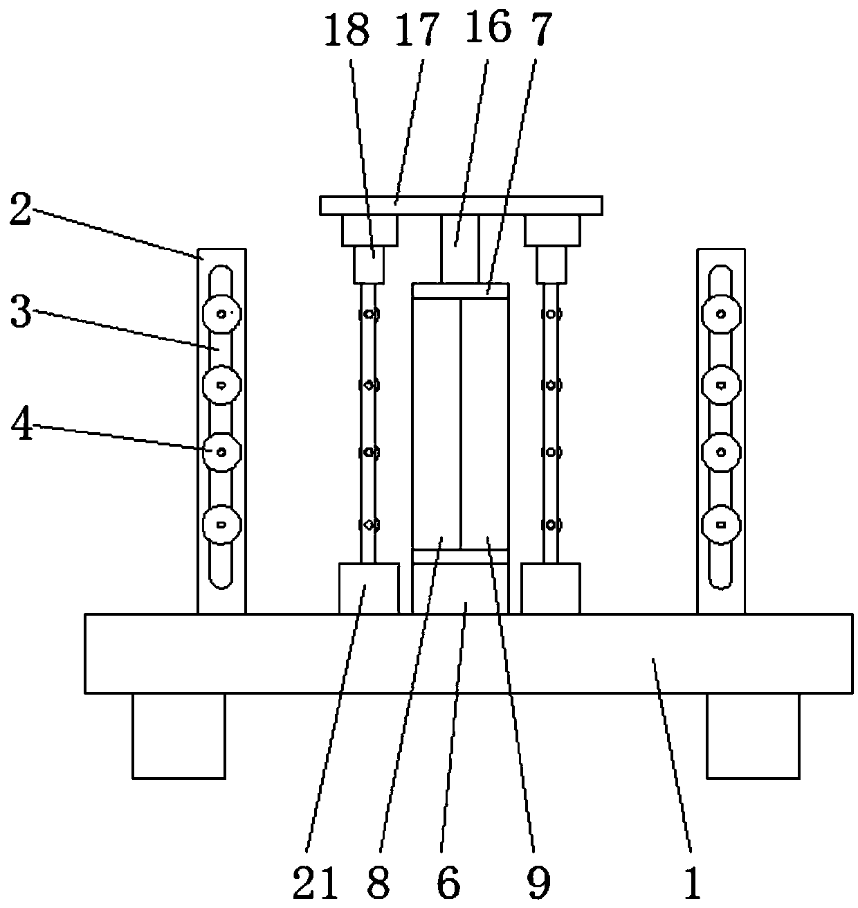
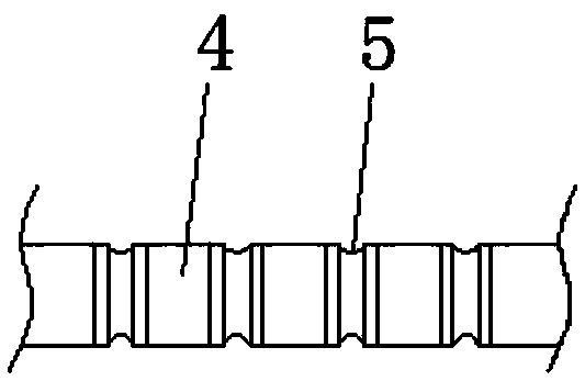
[0022] refer to Figure 1-5 , a yarn conveying and carding device, comprising a workbench 1, two supports 2 are arranged on the workbench 1, vertical strip-shaped installation holes 3 are arranged on both sides of each support 2, and two oppositely arranged strip-shaped mounting holes 3 are provided. A number of first guide rollers 4 are horizontally installed in the shape mounting hole 3 from top to bottom, and each first guide roller 4 is provided with evenly distributed first guide grooves 5, and a yarn carding roller is arranged between the two supports 2. Mechanism, the yarn carding mechanism includes a support frame 6, a frame 7, a first carding plate 8 and a s...


PUM


Abstract

The invention discloses a yarn conveying and carding device. The yarn conveying and carding device comprises a worktable. Two brackets are arranged on the worktable. Strip-shaped mounting holes are formed in the two sides of the brackets. First yarn guiding rollers are mounted in the strip-shaped mounting holes and provided with first yarn guiding grooves. A yarn carding mechanism is arranged between the two brackets and comprises a supporting frame, a frame, a first carding plate and a second carding plate. The first carding plate and the second carding plate are slidably connected with the frame. Vertical plates are arranged on the first carding plate and provided with first yarn guiding holes. Horizontal plates are arranged on the second carding plate and provided with second yarn guiding holes. A supporting column is arranged at the top of the supporting frame. A top cover is arranged at the top of the supporting column. Telescopic rods are fixedly connected to the positions, on the two sides of the supporting column, of the lower end of the top cover and fixedly connected with a plurality of second yarn guiding rollers. The second yarn guiding rollers are provided with yarn guiding pulleys. According to the yarn conveying and carding device, yarn can be prevented from being wound together, and it is ensured that the yarn is wound around a yarn barrel evenly and trimly.

Description

technical field [0001] The invention relates to the technical field of textile equipment, in particular to a yarn conveying and carding device. Background technique [0002] Most of the general yarn carding equipment uses a carding plate with a fixed needle plate structure to card the yarn. The working environment is limited, fragile and difficult to repair, and there are potential safety hazards in actual use. Therefore, we need a machine that can meet various working environments. , simple in structure, easy to manufacture, safe to use and capable of good combing of yarns, the sand thread carding device meets market demand. Contents of the invention [0003] The purpose of the present invention is to solve some problems in the prior art, and propose a kind of yarn conveying carding device. [0004] In order to achieve the above object, the present invention adopts the following technical solutions: [0005] A yarn conveying and carding device, comprising a workbench, o...

Claims


Application Information

Patent Timeline
Patent Type & Authority Applications(China)
IPC IPC(8): B65H57/14B65H57/04B65H57/06B65H59/10
CPCB65H57/14B65H57/04B65H57/06B65H59/10B65H2701/31
Inventor 夏平
Owner XIANGSHUI YONGTAI TEXTILE GARMENT CO LTD
Why Eureka
Try Eureka