Controller system and vacuum pump

A controller and vacuum pump technology, applied in pump control, pump testing, pump components, etc., to solve problems such as vacuum pumps not working properly

Inactive Publication Date: 2018-10-19
湖南江南汽车制造有限公司
View PDF3 Cites 1 Cited by
  • Summary
  • Abstract
  • Description
  • Claims
  • Application Information

AI Technical Summary

Problems solved by technology

Since the controller system controls the threshold value of the vacuum pump according to the atmospheric pressure of the plain, after the altitude increases, the controller system also controls the vacuum pump according to the threshold value under the standard atmospheric pressure value, which often causes the vacuum pump to fail to work normally.

Method used


Image

  • Controller system and vacuum pump

Examples


Embodiment 1

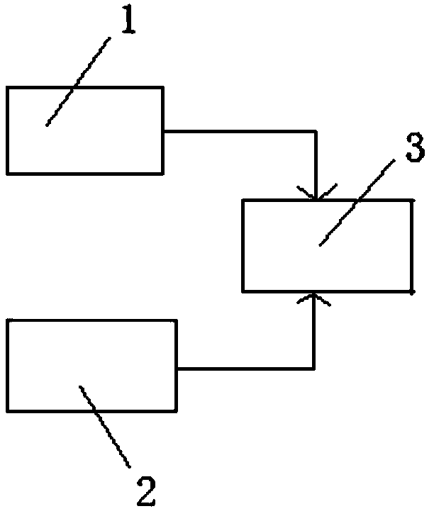
[0038] like figure 1 As shown, the present invention discloses a controller system, wherein the controller system includes an absolute pressure sensor 1 , a relative pressure sensor 2 and a controller 3 .

[0039] The absolute pressure sensor 1 can detect the altitude of the environment. The absolute pressure sensor 1 communicates with the atmosphere of the environment and can detect the pressure value of the environment. According to the detected pressure value, the pressure value signal can be converted into the corresponding pressure value by the conversion device. altitude signal. The absolute pressure sensor 1 can be a piezoresistive absolute pressure sensor 1 or a capacitive absolute pressure sensor 1 .

[0040] The relative pressure sensor 2 can detect the pressure value inside the vacuum pump.

[0041] Both the absolute pressure sensor 1 and the relative pressure sensor 2 are connected to the signal of the controller 3, and the controller 3 is connected to the signal...

Embodiment 2

[0044] In the second embodiment provided by the present invention, the structure of the controller system in this embodiment is similar to that in the first embodiment, and the similarities will not be repeated, and only the differences will be introduced.

[0045] In this embodiment, it is specifically disclosed that when the absolute pressure sensor 1 detects that the altitude is less than or equal to the first preset height value, the relative pressure sensor 2 detects that the pressure value is greater than or equal to the first opening pressure value and less than the first Stopping the pressure value, the controller 3 can control the vacuum pump to turn on, and when the relative pressure sensor 2 detects that the pressure value is greater than or equal to the first stop pressure value, the controller 3 can control the vacuum pump to turn off.

[0046] When the absolute pressure sensor 1 detects that the altitude is greater than the first preset height value and less than ...

Embodiment 3

[0058] The present invention discloses a vacuum pump, including the controller system described in any one of the above embodiments.

[0059] Since the vacuum pump provided by the present invention includes the controller system in any one of the above embodiments, the beneficial effects of the controller system are included in the vacuum pump disclosed in the present invention.

[0060] In the present invention, "first", "second", etc. are for distinction in description, and have no other special meanings.


PUM


Abstract

The invention discloses a controller system and a vacuum pump. The controller system comprises an absolute pressure sensor, a relative pressure sensor and a controller. The absolute pressure sensor iscapable of detecting the altitude of the environment. The relative pressure sensor is capable of detecting the pressure value inside the vacuum pump. The absolute pressure sensor and the relative pressure sensor are both connected with the controller through signals, the controller is connected with the vacuum pump through signals, and the controller can adjust the pressure value corresponding tothe start and stop of the vacuum pump according to the altitude signal output by the absolute pressure sensor. In use, the absolute pressure sensor transmits the detected altitude signal to the controller, and the controller adjusts the pressure value corresponding to the start and stop of the vacuum pump according to the detected altitude signal. The controller system can control the normal operation of the vacuum pump even after the external altitude changes.

Description

technical field [0001] The invention relates to the technical field of vacuum pumps, in particular to a controller system and a vacuum pump. Background technique [0002] At present, the controller system of the existing vacuum pump includes a controller and a relative pressure sensor. The relative pressure sensor transmits the detected atmospheric pressure to the controller, and the controller controls the opening and closing of the vacuum pump according to the received pressure signal. Since the controller system controls the threshold value of the vacuum pump according to the atmospheric pressure in the plain, after the altitude increases, the controller system also controls the vacuum pump according to the threshold value under the standard atmospheric pressure value, which often causes the vacuum pump to fail to work normally. [0003] Therefore, how the controller system can control the normal operation of the vacuum pump after the external altitude changes is a techni...

Claims


Application Information

Patent Timeline
Patent Type & Authority Applications(China)
IPC IPC(8): F04B51/00F04B49/06F04B39/00
CPCF04B51/00F04B39/00F04B49/06
Inventor 王大洋汪成伟席守军
Owner 湖南江南汽车制造有限公司
Why Eureka
Try Eureka