A Roots blower impeller

A Roots blower and impeller technology, which is applied in the direction of mechanical equipment, machines/engines, liquid fuel engines, etc., can solve the problems of uneven thermal deformation of the Roots blower impeller, and achieve the effect of small thermal deformation

Inactive Publication Date: 2019-08-30
CHANGSHA UNIVERSITY OF SCIENCE AND TECHNOLOGY
View PDF5 Cites 0 Cited by
  • Summary
  • Abstract
  • Description
  • Claims
  • Application Information

AI Technical Summary

Problems solved by technology

[0004] The problem to be solved by the present invention is to provide a Roots blower impeller with improved balance hole shape structure and controlled impeller thermal deformation for the technical problem of uneven thermal deformation of the Roots blower impeller.

Method used


Image

  • A Roots blower impeller
  • A Roots blower impeller
  • A Roots blower impeller

Examples


Embodiment

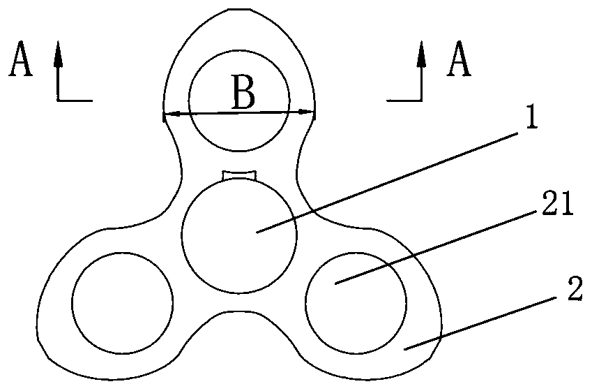
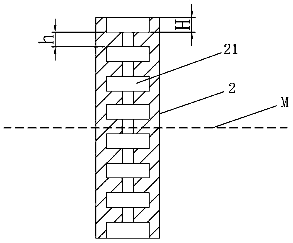
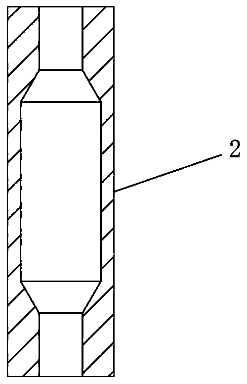
[0033] Such as figure 1 and figure 2 As shown, the Roots blower impeller of this embodiment has a center-symmetrical structure. The center of the Roots blower impeller is provided with an impeller shaft sleeve hole 1, and three impeller blades 2 are provided along the circumference of the impeller shaft sleeve hole 1. And each impeller blade 2 is provided with a balance hole 21, the balance hole 21 is a stepped cylindrical hole alternately stacked axially by a large-diameter cylindrical hole and a small-diameter cylindrical hole, and the axes of the large-diameter cylindrical hole and the small-diameter cylindrical hole coincide. The structure of the variable-section balance hole 21 adjusts the original uneven wall thickness of the impeller blade 2, so that the impeller can produce uniform thermal deformation, so as to control the wall thickness of the impeller blade 2 by adjusting the structure of the balance hole 21, and then The purpose of controlling the thermal deforma...


PUM


Abstract

The invention discloses a roots blower impeller. The roots blower impeller is of a central symmetry structure. An impeller shaft sleeve hole is formed in the center of the roots blower impeller, multiple impeller blades are arranged in the circumferential direction of the impeller shaft sleeve hole, each of the impeller blades is provided with a balance hole, and the balance holes are stepped cylindrical holes which are formed by alternately stacking of large cross-sectional columnar holes and small cross-sectional columnar holes in the axial direction. The roots blower impeller has the advantages of the improved balance hole structure and control over the amount of thermal deformation of the impeller.

Description

technical field [0001] The invention relates to a Roots blower component, in particular to a Roots blower impeller. Background technique [0002] The Roots blower is a volumetric rotary blower. Its working principle is to use two impellers to move relative to each other in the cylinder to compress and transport gas. Therefore, the normal meshing state of the two impellers during the rotation is the premise to ensure efficient gas delivery. [0003] The temperature of the Roots blower impeller will increase during the gas compression and delivery process. Due to the complex shape of the outer contour of the impeller and the uneven distribution of thickness, the impeller will produce uneven thermal deformation. This uneven thermal deformation makes the outer contour of the impeller The deformation causes the gap between the mating surfaces of the impeller to deviate from the normal state during the meshing process, which may cause local interference, aggravate the local wear o...

Claims


Application Information

Patent Timeline
Patent Type & Authority Patents(China)
IPC IPC(8): F04C18/12F04C29/00
Inventor 胡永乐周志海
Owner CHANGSHA UNIVERSITY OF SCIENCE AND TECHNOLOGY
Why Eureka
Try Eureka