Eureka AIR delivers breakthrough ideas for toughest innovation challenges, trusted by R&D personnel around the world.

Hydraulic torque converter with reversing dragging function

A hydraulic torque converter and functional technology, applied in the field of mechanical design, can solve problems such as difficulty in starting, and achieve the effects of expanding functions, increasing fuel economy, and improving transmission efficiency

Inactive Publication Date: 2018-10-19
SHAANXI AEROSPACE POWER HIGH TECH
View PDF4 Cites 0 Cited by
  • Summary
  • Abstract
  • Description
  • Claims
  • Application Information

AI Technical Summary

Problems solved by technology

[0006] In order to solve the problem that traditional heavy-duty high-mobility vehicles and special vehicles are difficult to start in low-temperature environments, the invention provides a hydraulic torque converter with anti-drag function

Method used


Image

  • Hydraulic torque converter with reversing dragging function
  • Hydraulic torque converter with reversing dragging function
  • Hydraulic torque converter with reversing dragging function

Examples


Embodiment 1

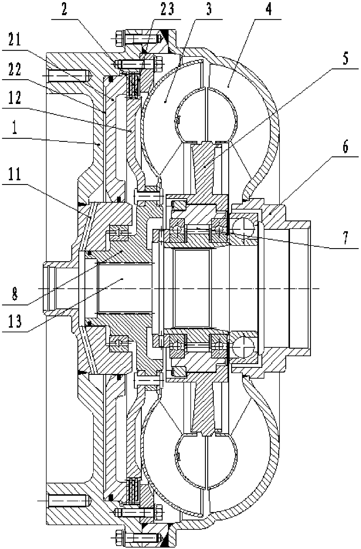
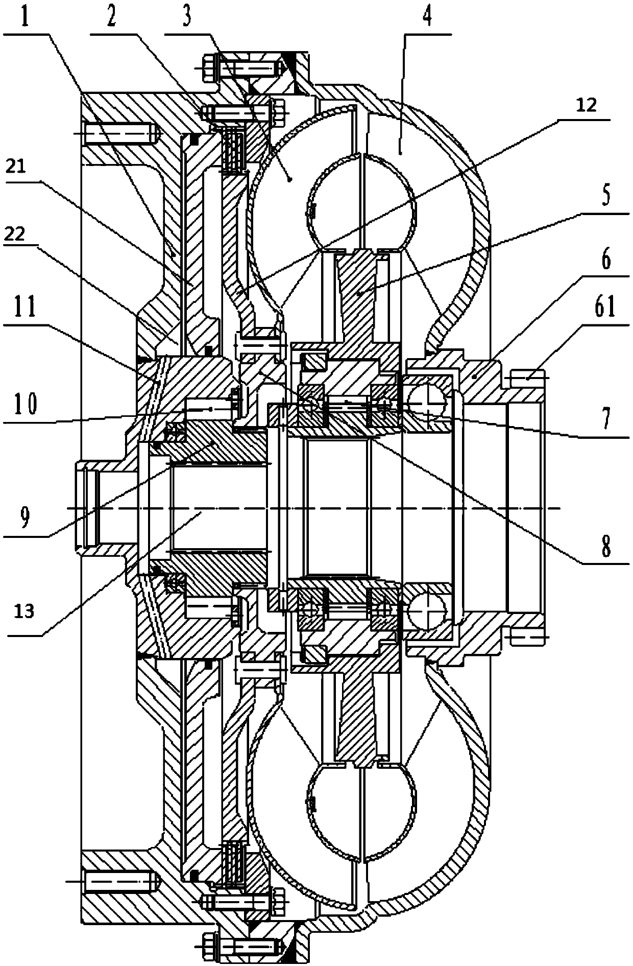
[0025] see figure 2 , the hydraulic torque converter of this embodiment is in figure 1 An anti-drag device is added to the structure of the conventional torque converter with a lock-up clutch, specifically, an anti-drag device consisting of an anti-drag inner ring 9 and a second one-way clutch 10 is added inside the cover wheel 1; The inner ring 9 is arranged on the output shaft of the conventional hydraulic torque converter; the end of the outer wall of the anti-drag inner ring 9 away from the cover wheel 1 is splined to the turbine hub 8, and the middle part of the outer wall of the anti-drag inner ring 9 is connected to the second unit It is fixedly connected to the inner ring of the clutch 10; the outer ring of the second one-way clutch 10 is fixedly connected to the cover wheel 1; when the power is input from the output shaft, the second one-way clutch 10 is in a locked state; When inputting, the second one-way clutch 10 is in an overrunning state. The second one-way c...

Embodiment 2

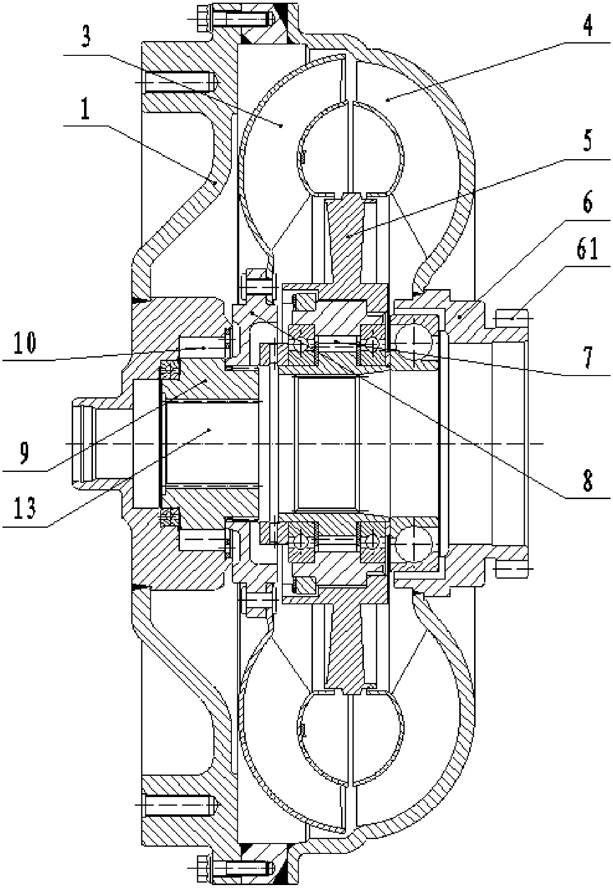
[0035] see image 3 In this embodiment, an anti-drag device is added to the structure of a traditional hydraulic torque converter without a lock-up clutch. The difference from Embodiment 1 is that the lock-up clutch 2 and the torque converter lock-up oil passage 11 are omitted in this embodiment. The hydraulic torque converter of this embodiment can work in the following working conditions:

[0036] 1. Hydraulic working condition

[0037] When the vehicle starts and climbs, the hydraulic torque converter works in the hydraulic condition, at this time the second one-way clutch 10 is opened (in the overrunning state), and the power transmission route is: cover wheel 1→pump wheel 4→turbine 3 →turbine hub 8→anti-drag inner ring 9→output shaft 13.

[0038] 2. Anti-drag working condition

[0039] After the vehicle has been stationary for a long time in a low temperature environment, it is difficult to start the vehicle due to the relatively low ambient temperature and the relativ...

Embodiment 3

[0042] This embodiment is based on the structure of Embodiment 1 or 2, and a power take-off gear 61 is set on the pump hub 6. When the vehicle is stationary, the engine is started. Full power power is taken at 61, and the power transmission route is: cover wheel 1→pump wheel 4→pump hub 6→power take-off gear 61. All the other working conditions are identical with embodiment 1 or 2.


PUM


Abstract

In order to solve the problem that traditional heavy type high motor vehicles and special vehicles are difficult to start at the low temperature environment, the invention provides a hydraulic torqueconverter with a reversing dragging function. The hydraulic torque converter is characterized in that a reversing dragging device arranged inside a cover wheel is further included; the reversing dragging device comprises a reversing dragging inner ring and a second one-way clutch, the reversing dragging inner ring is arranged on an output shaft, the end, far away from the cover wheel, of the outerwall of the reversing dragging inner ring is connected with a turbine hub through splines, and the middle portion of the outer wall of the reversing dragging inner ring is fixedly connected with an inner ring of the second one-way clutch; and the outer ring of the second one-way clutch is fixedly connected with the cover wheel, when power is input from the output shaft, the second one-way clutchis located in the locking state, and when the power is input from the cover wheel, the second one-way clutch is in the surpass state. Torque of the hydraulic torque converter can be transmitted to thereversing dragging inner ring from the output shaft and is then transmitted to the second one-way clutch through the reversing dragging inner ring, the second one-way clutch then transmits the torqueto the cover wheel, the toque is finally transmitted to an engine from the cover wheel to drive the engine to rotate, and dragging starting or sliding starting can be achieved.

Description

technical field [0001] The invention belongs to the technical field of mechanical design, and in particular relates to a hydraulic torque converter suitable for chassis of heavy-duty high motor vehicles and special vehicles. Background technique [0002] The structure of the traditional hydraulic torque converter used on the existing heavy-duty high-mobility vehicles and special vehicles is as follows: figure 1 As shown, it includes a cover wheel 1, a turbine 3, a turbine hub 8, a pump wheel 4, a pump hub 6, a guide wheel 5, and an output shaft 13; the turbine 3 is installed on the output shaft 13 through the turbine hub 8, and the pump wheel 4 passes through the pump hub 6 is installed on the output shaft 13; the cover wheel 1, the turbine wheel 3 and the pump wheel 4 are set in sequence; the cover wheel 1 is fixedly connected with the pump wheel 4; the guide wheel 5 is set between the turbine wheel 3 and the pump wheel 4, through the one-way clutch 7 Installed on the outp...

Claims


Application Information

Patent Timeline
IPC IPC(8): F16H45/02F16H61/14
CPCF16H45/02F16H61/14F16H2045/007
Inventor 刘兴国王宏卫王涛赵紫苓颜燕琼王宇飞严周维黄龙黄显臣邢红亮
Owner SHAANXI AEROSPACE POWER HIGH TECH
Why Eureka
Eureka Blog
Learn More