
Quick coupling male component capable of automatically relieving pressure

An automatic unloading and male head technology, applied in the direction of mechanical equipment, couplings, etc., can solve the problems of large structural restrictions, unstable supply pressure, bulges, etc., to improve stability and reliability, and reduce swelling and damage , the effect of reducing economic losses

Inactive Publication Date: 2018-10-19
CHINA AVIATION OPTICAL-ELECTRICAL TECH CO LTD
View PDF5 Cites 2 Cited by
  • Summary
  • Abstract
  • Description
  • Claims
  • Application Information

AI Technical Summary

Problems solved by technology

[0003] 2. The liquid cooling system operates under the rated pressure, and the system may have unstable supply pressure. When the pressure mutation is greater than the safe pressure of the module, the module will be damaged and bulged.
[0007] Due to the small internal space and large structural restrictions of the quick connector male assembly, the current blind-mating quick connector male assembly does not have a self-relieving function in the entire industry
However, in the industry, the self-relieving function of the ball-locking quick connector male head component is only realized by domestic manufacturers on products with an effective diameter greater than 10mm. The specific solution is to hollow out the inside of the sealed terminal and install a spring inside the sealed terminal. O-shaped sealing rubber ring, spring and other parts are realized. The biggest problem of this solution is that it can only be realized when the structural space of the quick connector male head assembly is sufficient. Products with an effective diameter below 10mm cannot realize the self-relieving function.

Method used


Image

  • Quick coupling male component capable of automatically relieving pressure
  • Quick coupling male component capable of automatically relieving pressure
  • Quick coupling male component capable of automatically relieving pressure

Examples


Embodiment Construction

[0018] The specific implementation manners of the present invention will be further described below in conjunction with the accompanying drawings.

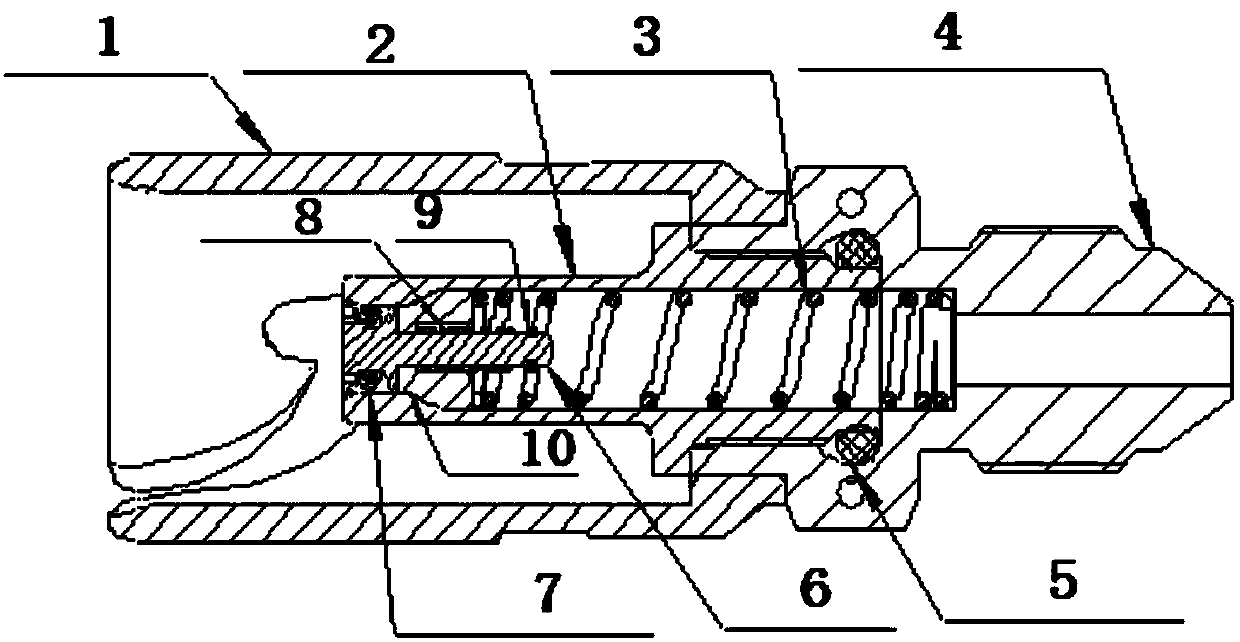
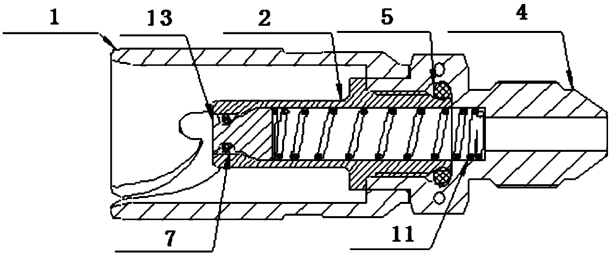
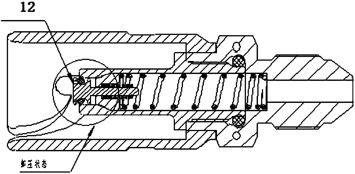
[0019] The inventive idea of ​​the present invention is as follows: when the internal space pressure formed by the quick connector male assembly and the module is lower than the pressure value P1, the quick connector male assembly realizes the self-sealing function; when the internal space pressure formed by the quick connector male assembly and the module When the value is higher than P1 and smaller than P2, the quick connector male assembly will automatically release the pressure to discharge the internal pressure to protect the module from being exploded by the sharply increased pressure; when the internal pressure of the module drops to P3 after the pressure is discharged, the pressure relief will be closed , The quick connector male head assembly re-realizes the self-sealing function. Among them, 0~P1 is the self-sealing work...


PUM


Abstract

The invention belongs to the technology of a fluid transmission connector in the field of electronic liquid heat dissipation, and relates to a quick coupling male component capable of automatically relieving pressure. The quick coupling male component comprises a connecting nut, a male disk shell II, an O-shaped rubber ring I, a male disk shell I and an O-shaped rubber ring II. The quick couplingmale component is characterized by also comprising a cylinder spring I, a sealing rod, a cylinder spring II, a snap spring and a sealing block. When the inner pressure of the quick coupling is lower than a designed pressure relief value, the sealing rod and the sealing block are integrated and reach an effect of sealing. When the inner pressure of the quick coupling reaches the designed pressure relief value, the sealing rod is separated from the sealing block and protrudes forwards to realize a function of automatic pressure relief. By using the fluid connector capable of automatically relieving pressure, the automatically relieving pressure can improve the safety of a liquid cooling system, greatly reduces the phenomenon that a module is broken and damaged due to pressure jump or temperature change, further improves the stability and reliability of the system, and reduces financial loss.

Description

technical field [0001] The invention belongs to fluid transmission connector technology in the field of electronic liquid heat dissipation, and relates to a quick connector male assembly capable of automatic pressure relief. Background technique [0002] 1. During the operation or debugging of the liquid cooling system, it is often necessary to maintain the liquid cooling module in the system. After the shutdown, the pressure in the liquid cooling module may not be completely removed. High, the liquid inside the module expands when heated, the pressure increases sharply, and the pressure is enough to burst the module; [0003] 2. The liquid cooling system operates under the rated pressure, and the supply pressure of the system may be unstable. When the sudden change in pressure is greater than the safe pressure of the module, the module will be damaged and bulged. [0004] In the above two application environments, the internal pressure of the module rises sharply. Since th...

Claims


Application Information

Patent Timeline
IPC IPC(8): F16L37/084
CPCF16L37/0842
Inventor 谢地姚志敏冯亚利曹海军蔡艳召
Owner CHINA AVIATION OPTICAL-ELECTRICAL TECH CO LTD
Learn More