A method for measuring magneto-optical Kerr signal
What is AI technical title?
AI technical title is built by Patsnap AI team. It summarizes the technical point description of the patent document.
A signal measurement, magneto-optical Kerr technology, applied in magnetic properties measurement, magnetization measurement, magnetic field measurement using magneto-optical equipment, etc., can solve problems affecting measurement accuracy, affecting signal accuracy, and low signal-to-noise ratio , to reduce the impact of stray light, improve the signal-to-noise ratio, and reduce the impact
Active Publication Date: 2020-07-03
嘉兴诺恩医疗科技有限公司
View PDF4 Cites 2 Cited by
Summary
Abstract
Description
Claims
Application Information
AI Technical Summary
This helps you quickly interpret patents by identifying the three key elements:
Problems solved by technology
Method used
Benefits of technology
Problems solved by technology
Defect 1 of the existing technology: In the Kerr angle measurement experiment, some non-magnetic effects such as linear birefringence and linear dichroism will affect the accuracy of the measurement, and will also affect the polarization state of light. These effects are not only caused by the sample , also comes from the device itself; defect 2 of the prior art: the Kerr angle measurement experiment in the prior art usually adopts the scheme that the light beam propagates between the optical elements in the atmosphere, which is easily affected by the positional deviation of the optical elements, Affect the accuracy of the signal; defect three of the prior art: the light intensity of the local region of the sample surface detected by the traditional near-field Kerr microscope is relatively weak, resulting in a low signal-to-noise ratio, and the magneto-optical Kerr signal measurement method can Solve the problem
Method used
Image
Click on the blue label to locate the original text in one second.
Reading with bidirectional positioning of images and text.
Examples
Embodiment Construction
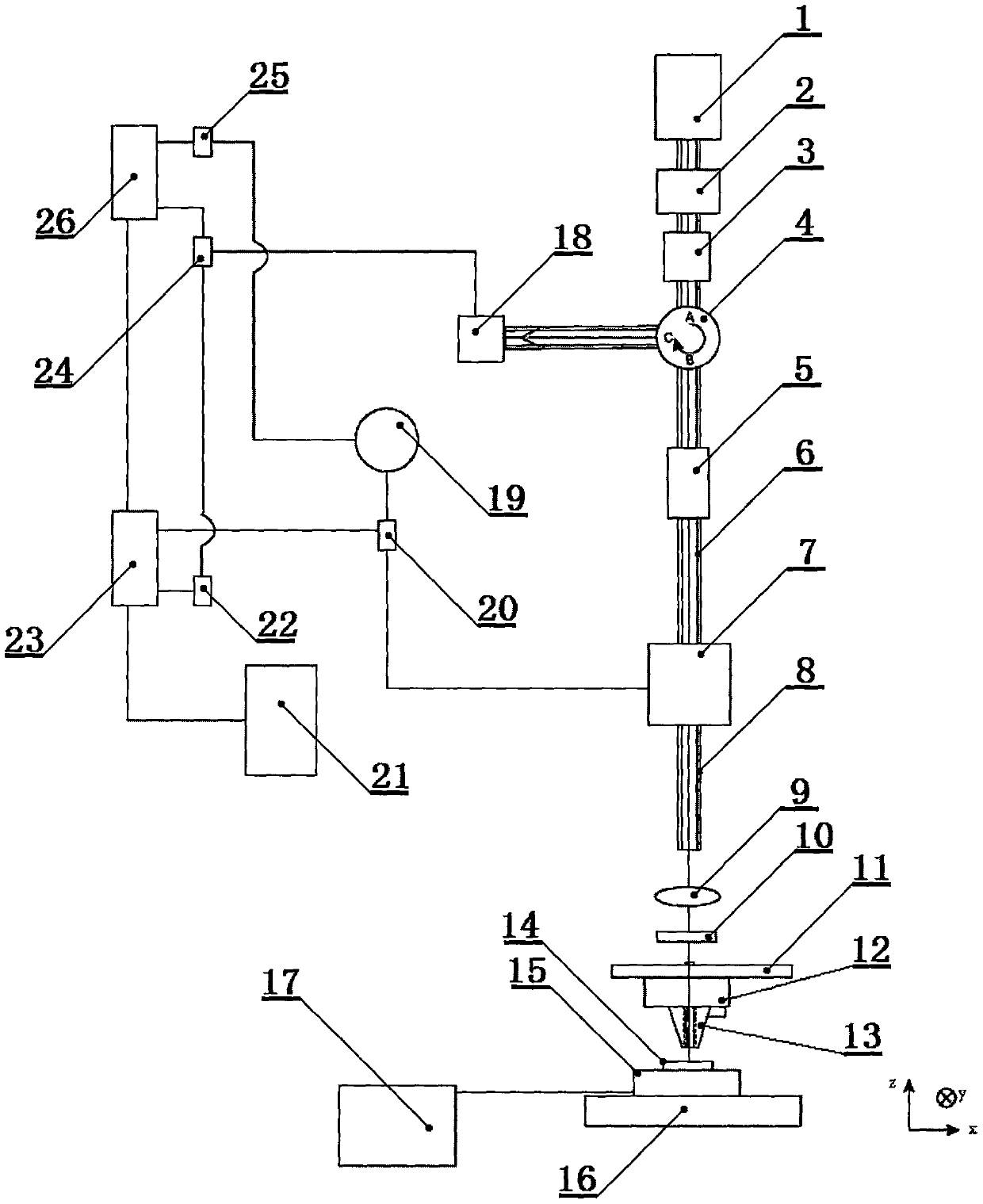
[0022] Such as figure 1It is a schematic diagram of the present invention, the lower right corner has an xyz three-dimensional direction mark, xyz is a spatial rectangular coordinate system, the xy plane is a horizontal plane, and the zx plane is perpendicular to the horizontal plane. The measuring device mainly includes a laser 1, a polarization controller 2, an isolator 3, and a polarization-maintaining ring 4, polarizer 5, polarization maintaining fiber I6, electro-optic modulator 7, polarization maintaining fiber II8, aspheric mirror 9, 1 / 4 wave plate 10, lens stand 11, atomic force microscope 12, probe 13, sample 14, magnet 15 , sample stage 16, power supply 17, photodetector 18, signal generator 19, power divider I20, computer 21, low-pass filter 22, lock-in amplifier I23, frequency multiplier 24, power divider II25, lock-in amplifier II26. The incident light path and the reflected light path. The isolator 3 has two ports, the entrance and the exit, and the light beam ca...
PUM
Property
Measurement
Unit
width
aaaaa
aaaaa
diameter
aaaaa
aaaaa
length
aaaaa
aaaaa
Abstract
The invention relates to the field of magnetic measurement of material surfaces, in particular to a magneto-optical Kerr signal measuring method. The measuring device comprises a laser, a polarizationcontroller, an isolator, a polarization-maintaining circulator, a polarizer, a polarization-maintaining fiber I, an electro-optic modulator, a polarization-maintaining fiber II, an aspherical mirror,a quarter-wave plate, a lens stage, an atomic force microscope, a probe, a sample, a magnet, a sample stage, a power supply, a photodetector, a signal generator, a power distributor I, a computer, alow-pass filter, a lock-in amplifier I, a frequency multiplier, a power distributor II, a lock-in amplifier II, an incident optical path, and a reflective optical path; the probe has a through hole; and the interferential method of two orthogonal polarization components of the same beam are used to obtain the Kerr angle information of the sample, and the influence of certain non-magnetic effects such as linear birefringence and linear dichroism from the device itself, on the measurement accuracy is reduced; and a main optical path is in the fiber, optical components in the optical path are reduced, the influence of stray light is lowered, and the signal to noise ratio is improved.
Description
technical field [0001] The invention relates to the field of material surface magnetic measurement, in particular to a magneto-optical Kerr signal measurement method for studying the magneto-optical Kerr signal on the material surface by using a single-beam interference method. Background technique [0002] The magneto-optical Kerr effect measurement device is an important means in the study of material surface magnetism. Its working principle is based on the magneto-optic Kerr effect caused by the interaction between light and magnetized media. Magnetic detection, and non-contact measurement can be realized, and it has important applications in the research of magnetic order, magnetic anisotropy, interlayer coupling and phase transition behavior of magnetic ultrathin films. The magneto-optical Kerr effect measurement device is mainly used to observe the magnetization of the sample surface by detecting the change of the polarization state of a beam of linearly polarized ligh...
Claims
Application Information
Patent Timeline
Application Date:The date an application was filed.
Publication Date:The date a patent or application was officially published.
First Publication Date:The earliest publication date of a patent with the same application number.
Issue Date:Publication date of the patent grant document.
PCT Entry Date:The Entry date of PCT National Phase.
Estimated Expiry Date:The statutory expiry date of a patent right according to the Patent Law, and it is the longest term of protection that the patent right can achieve without the termination of the patent right due to other reasons(Term extension factor has been taken into account ).
Invalid Date:Actual expiry date is based on effective date or publication date of legal transaction data of invalid patent.

