Optical sensing device for restraining voltage sensor temperature error

A technology of temperature error and optical sensing, applied in the direction of measuring device, voltage/current isolation, special recording/indicating device, etc., can solve problems such as reciprocity degradation

Active Publication Date: 2016-08-31
安徽华驰动能科技有限公司
View PDF5 Cites 11 Cited by
  • Summary
  • Abstract
  • Description
  • Claims
  • Application Information

AI Technical Summary

Problems solved by technology

[0006] The present invention aims at the complex temperature-changing environment of the smart grid, which will lead to the problem of reciprocity degradation of the Pockels phase sensitive unit in the reflective double-crystal optical voltage sensor. At the same time, in order to control the temperature error generated by the do

Method used


Image

  • Optical sensing device for restraining voltage sensor temperature error
  • Optical sensing device for restraining voltage sensor temperature error
  • Optical sensing device for restraining voltage sensor temperature error

Examples


Embodiment Construction

[0053] The present invention will be described in detail below in conjunction with the accompanying drawings and embodiments.

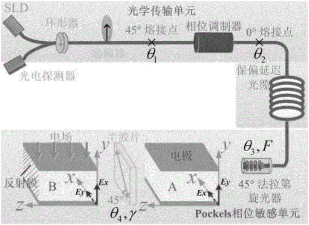
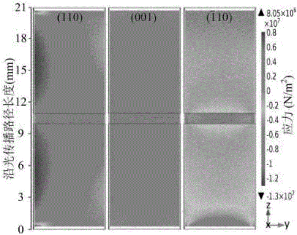
[0054] The complex temperature-changing environment of the smart grid will lead to: the key parameters that affect the temperature stability of the optical voltage sensor (σ y -σ z ) in the two BGO crystals are inconsistently distributed, which destroys the compensation effect of the reciprocal double crystal structure and generates temperature errors. By analyzing the influence of key parameters on the reciprocity of the Pockels phase sensitive unit, a reasonable structural design is carried out to suppress these adverse effects, so as to ensure its good reciprocity in the complex temperature-changing environment of the smart grid.

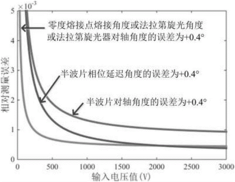
[0055] The unsatisfactory optical devices and optical path welding points in the optical transmission unit and Pockels phase sensitive unit will lead to the measurement error of the optical voltage sensor. By studying t...


PUM


Abstract

The invention discloses an optical sensing device for restraining a voltage sensor temperature error and belongs to the field of an optical voltage sensor. The optical sensing device comprises an optical transmission unit and a Pockels phase sensing unit. The reciprocity degeneration of the Pockels phase sensing unit is caused by the inconsistency of the temperature fields and stress fields of two crystals; and the generation of a measuring error of the optical voltage sensor is caused by the influence of the non-ideal welding angle and counter shaft angle of the optical transmission unit on the magnitude of interference light intensity and feedback phase. By establishing a temperature error model of the optical transmission unit and the Pockels phase sensing unit, a novel optical base structure for counteracting additional stress birefringence in the two crystals is designed, and an angle error compensating method is provided, so that the measuring precision and temperature stability of the optical voltage sensor are increased.

Description

technical field [0001] The invention belongs to the technical field of optical voltage sensors, and in particular relates to an optical sensing device for suppressing temperature errors of voltage sensors. Background technique [0002] The power system is the lifeblood of the national economy, and the power industry is directly related to the healthy and stable development of the national economy. With the development of the power industry, the transmission capacity of the power system continues to increase, and the voltage operation level is getting higher and higher. The power grid is developing in the direction of digitization, intelligence and networking. The smart grid is the intelligence of the power grid. It is based on an integrated, high-speed two-way communication network, through the application of advanced sensing and measurement technology, advanced equipment technology, advanced control method and advanced decision support system technology. , to achieve the g...

Claims


Application Information

Patent Timeline
IPC IPC(8): G01R15/24G01D3/036
CPCG01D3/036G01R15/242
Inventor 李慧付志达王夏霄李立京孟照魁徐宏杰
Owner 安徽华驰动能科技有限公司
Why Eureka
Try Eureka