An Angle Measurement Method Combining Steering Vector Correlation and Local Focusing
What is AI technical title?
AI technical title is built by Patsnap AI team. It summarizes the technical point description of the patent document.
A technology of guiding vector and angle measurement, which is applied in the direction of measuring angle, measuring device, radio wave measuring system, etc. It can solve problems such as poor angle measurement effect, error in defuzzification algorithm, and decrease in angle measurement performance.
Active Publication Date: 2019-04-02
BEIJING INSTITUTE OF TECHNOLOGYGY
View PDF2 Cites 0 Cited by
Summary
Abstract
Description
Claims
Application Information
AI Technical Summary
This helps you quickly interpret patents by identifying the three key elements:
Problems solved by technology
Method used
Benefits of technology
Problems solved by technology
In this method, vector average is carried out on the measured values of phase difference at various levels measured multiple times, and the estimated value of phase difference after vector average is used to perform successive recursive defuzzification angle measurement. This method can improve the estimation accuracy of phase difference in the process of defuzzification. But it will cause recursive errors to propagate step by step, and even lead to errors in the defuzzification algorithm
[0004] In 2013, Wang Tiedan et al. proposed a compressed sampling matching tracking method based on the article "DOAestimation of coherently distributed sources based on block-sparse constraint with measurement matrix uncertainty" on pages 1-8 of the 6th issue of the journal "IEICE Electronics Express". Improved block sparse signal matching pursuit method, which has good robustness, but in the case of low SNR, due to the increase of non-zero elements in sub-blocks, the angle measurement performance of this method drops sharply
This method has good angle measurement performance, but under non-ideal conditions such as low signal-to-noise ratio and small number of snapshots, the angle measurement effect is not good
[0007] Considering the above angle measurement methods comprehensively, there is no angle measurement method that can effectively solve the angle measurement error accumulation problem of the successive recursive de-phase ambiguity method, improve the angle measurement performance under low signal-to-noise ratio, and reduce the amount of calculation
Method used
Image
Click on the blue label to locate the original text in one second.
Reading with bidirectional positioning of images and text.
Examples
Embodiment 1
[0073] In this embodiment, the array antenna is a multi-element linear array, and the angle measurement method provided by the present invention will be described in detail by taking the M-element linear array as an example.
[0074] When the array antenna is an M-element line array, the angle measurement method provided by the present invention is specifically:
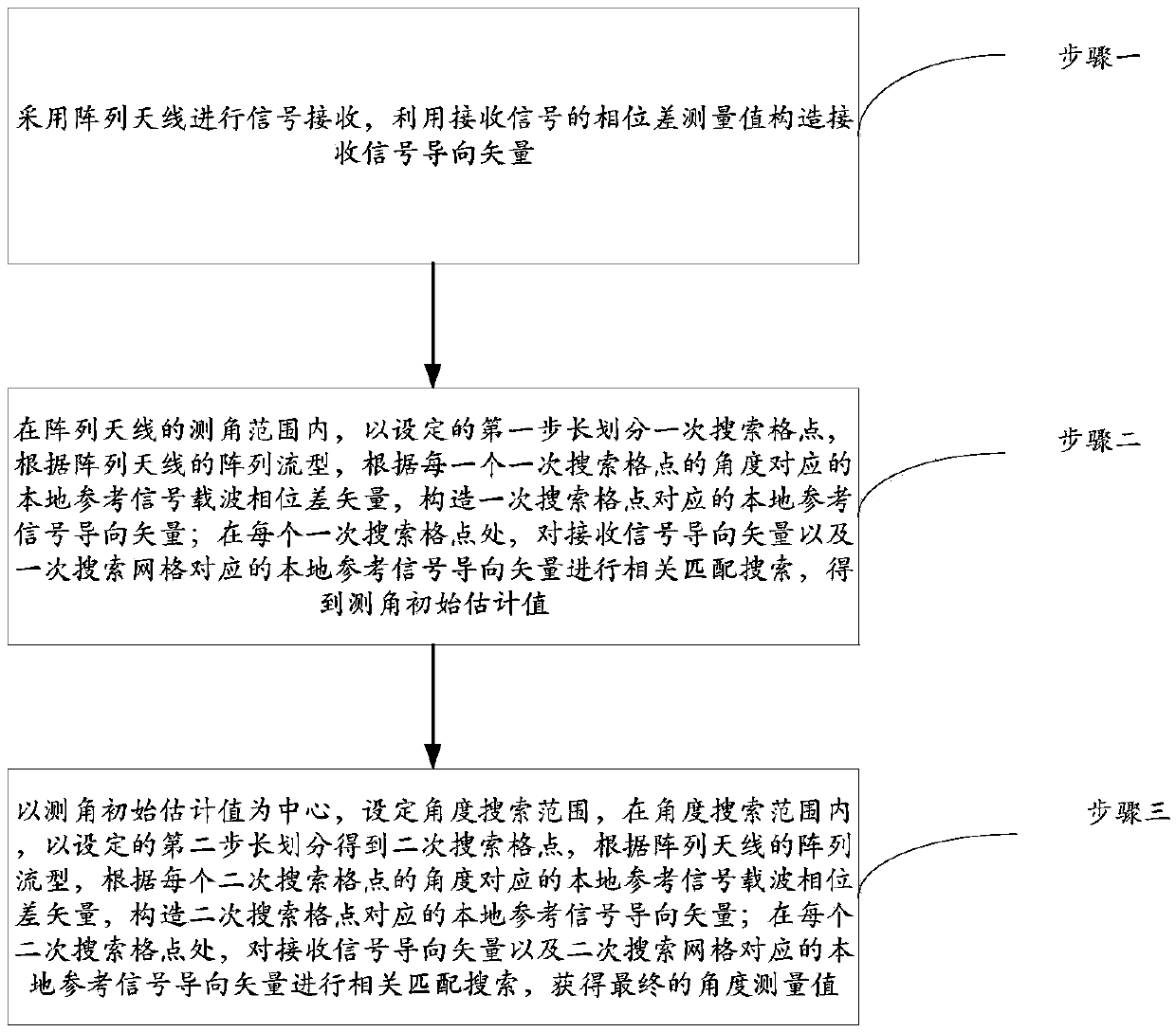
[0075] Step 1. The array antenna is used for signal reception, and the phase difference measurement value of the received signal is used to construct the steering vector of the received signal.
[0076] This step one includes the following specific steps:
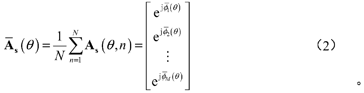
[0077] S101: The received signal of the M-element linear array includes N measured values, and N steering vectors A are constructed according to the N measured values s (θ,n):
[0078]
[0079] Where θ is the target incident angle; m=1,2,...,M; n=1,2,...,N.
[0080] φ m,n (θ) = πh m sinθ+Δφ m,n is the carrier phase difference measurement value of the nth ...
Embodiment 2
[0123] In this embodiment, the carrier wavelength λ=3cm is set, the antenna array is a four-baseline non-equidistant linear array of M=4, and the antenna element spacing d m =λ / 2·[-15,-5,5,15]. An angle measurement operation is performed in 1 ms, and the number of samples of raw data measurement values is N=1000. Set the incident angle of the stationary target to 60°, the length of the first step to 0.1°, and the initial value preset threshold ξ=1°. The second step size is 0.01°, the second search range parameter θ range = 0.2°. The carrier phase error follows a Gaussian white noise distribution with a standard deviation of 10°.
[0124] Step 1: Store N=1000 array received signal carrier phase difference measurements, and construct the received signal steering vector A s (θ,n):
[0125]
[0126] In formula (13), φ m,n (θ) = πh m sinθ+Δφ m,n , m=1,2,3,4 means the carrier phase difference measurement value of the nth observation sample of the mth measurement channel...
PUM
Abstract
The invention discloses a guide vector correlation and local focusing combined angle measurement method, and the method can improve the angle measurement performances and reduce the calculation burden. The method comprises the following steps: receiving a signal through an array antenna, and constructing a received signal guide vector through a phase difference measurement value of the received signal; dividing primary search grid points at a set second step in an angle measurement range of the antenna array, carrying out the correlation matching search of the received signal guide vector anda local reference signal guide vector corresponding to the primary search grid point at each primary search grid point, and obtaining an initial estimation value of angle measurement; taking the initial estimation value of angle measurement as the center, setting an angle search range, carrying out the dividing at a set second step to obtain secondary search grid points, carrying out the correlation matching search of the received signal guide vector and a local reference signal guide vector corresponding to the secondary search grid point at each secondary search grid point, and obtaining a final estimation value of angle measurement, wherein the set second step is shorter than the set first step.
Description
technical field [0001] The invention relates to the technical field of microwave radar measurement, in particular to an angle measurement method combining steering vector correlation and local focusing. Background technique [0002] In the field of space rendezvous and docking radar measurement, space target angle measurement is an important function of rendezvous and docking radar. There are several types of angle measurement methods for radar measurement: interferometer phase comparison method, subspace angle measurement method, subspace fitting angle measurement method, and compressive sensing based angle measurement method. [0003] In September 2011, Han Yuetao proposed a successive recursive solution based on phase difference vector average fuzzy method. In this method, vector average is carried out on the measured values of phase difference at various levels measured multiple times, and the estimated value of phase difference after vector average is used to perfor...
Claims
Application Information
Patent Timeline
Application Date:The date an application was filed.
Publication Date:The date a patent or application was officially published.
First Publication Date:The earliest publication date of a patent with the same application number.
Issue Date:Publication date of the patent grant document.
PCT Entry Date:The Entry date of PCT National Phase.
Estimated Expiry Date:The statutory expiry date of a patent right according to the Patent Law, and it is the longest term of protection that the patent right can achieve without the termination of the patent right due to other reasons(Term extension factor has been taken into account ).
Invalid Date:Actual expiry date is based on effective date or publication date of legal transaction data of invalid patent.


