Convenient electrical cabinet

An electrical cabinet and convenient technology, applied in the field of electrical cabinets, can solve the problems of low labor intensity, high labor intensity, long time consumption, etc., and achieve the effect of reducing pulling intensity, improving flexibility, and low labor intensity

Active Publication Date: 2018-10-19
唐山励德成套设备有限公司
View PDF11 Cites 4 Cited by
  • Summary
  • Abstract
  • Description
  • Claims
  • Application Information

AI Technical Summary

Problems solved by technology

[0003] In order to solve the above problems, the present invention provides an easy-to-use electrical cabinet, which can solve the problem of manually leveling the installation position of the electrical cabinet and manually fixing the electrical cabinet in the process of using the temporary electrical cabinet on the existing construction site. It is necessary to manually move the electrical cabinet with the help of existing hoisting equipment. Temporary electrical cabinets need to be assembled on site, which takes a long time. Manual leveling of the installation position is labor-intensive. The cost of manually moving the electrical cabinet with the help of hoisting equipment is high. The fixing stability of the electrical cabinet is poor, and it is easy to reduce the service life of the electrical cabinet due to collision in the process of transporting the electrical cabinet. The labor intensity is high and the work efficiency is low. It can realize the function of convenient operation of the temporary electrical cabinet on the construction site. There is no need to manually assemble electrical cabinets, no need to manually level the working surface, and it has the advantages of good stability, short time consumption, low labor intensity and high work efficiency.

Method used


Image

  • Convenient electrical cabinet
  • Convenient electrical cabinet
  • Convenient electrical cabinet

Examples


Embodiment Construction

[0023] In order to make the technical means, creative features, objectives and effects of the present invention easy to understand, the present invention will be further explained in conjunction with specific drawings.

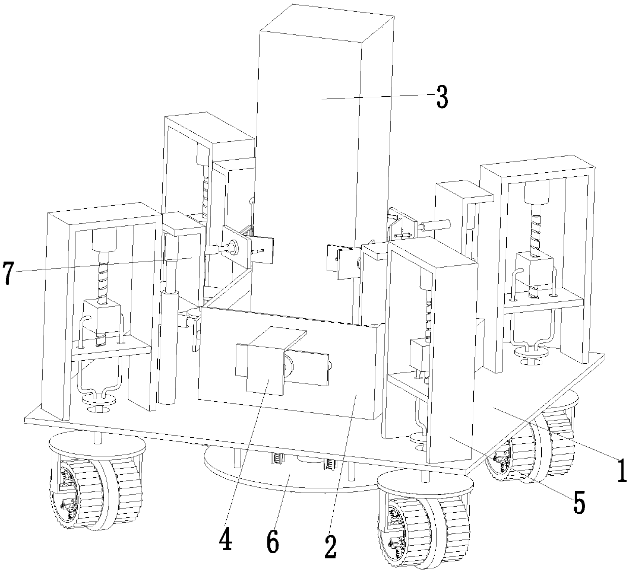
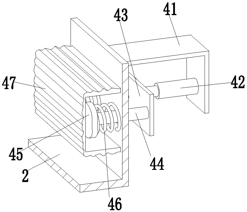
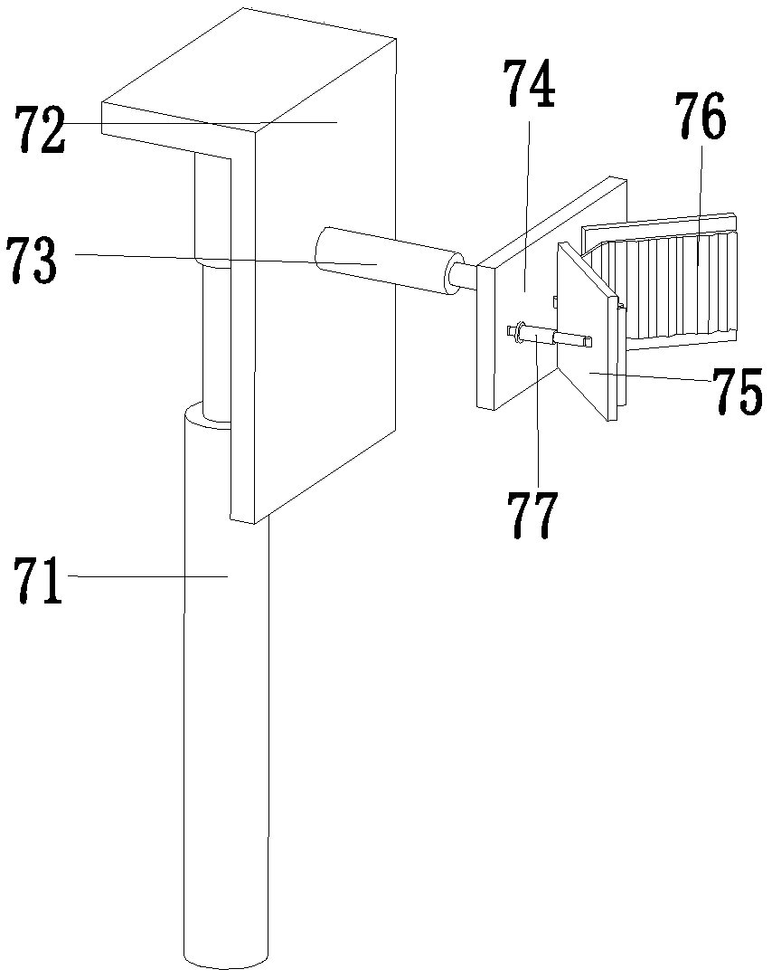
[0024] Such as Figure 1 to Figure 5 As shown, a convenient electrical cabinet includes a bottom plate 1, an auxiliary limit frame 2 is installed on the bottom plate 1, an electric cabinet body 3 is placed in the auxiliary limit frame 2, and an auxiliary tightening frame is provided on the auxiliary limit frame 2. The number of auxiliary abutment holes is four, and they are respectively arranged around the auxiliary limit frame 2. There are auxiliary abutment devices 4 in the auxiliary abutment holes, and four clamping devices 7 are installed on the bottom plate 1. The clamping devices 7 are respectively located at the top corners of the auxiliary limit frame 2. The bottom plate 1 is provided with four sliding holes, the sliding holes are provided with a mobile f...


PUM


Abstract

The invention relates to a convenient electrical cabinet which comprises a bottom plate. An auxiliary limit frame is installed on the bottom plate, an electric cabinet body is arranged in the auxiliary limit frame, and auxiliary abutting holes are arranged in the auxiliary limit frame. The auxiliary abutting holes are internally provided with auxiliary abutting devices, and clamping devices are installed on the bottom plate. Sliding holes are arranged in the bottom plate, moving and fixing devices are arranged in the sliding holes, and a positioning device is arranged in the middle of the lower end of the bottom plate. In the process of using a temporary electrical cabinet in an existing construction site, the installation position of the electrical cabinet needs to be manually levelled, the electrical cabinet needs to be manually fixed, the manual movement of the electrical cabinet needs existing lifting equipment, the temporary electrical cabinet needs to be assembled in the site, along time is taken, the labor intensity is high when the installation position of the electrical cabinet is manually levelled, the cost is high when the electrical cabinet is manually moved with the existing lifting equipment, the electrical cabinet is manually fixed by ropes, the stability is poor, and the above problems are solved according to the convenient electrical cabinet.

Description

Technical field [0001] The invention relates to the field of power equipment, in particular to a convenient electrical cabinet. Background technique [0002] The electrical cabinet is a cabinet made of steel to protect the normal working of components. The materials for making electrical cabinets are generally divided into two types: hot-rolled steel sheet and cold-rolled steel sheet. Compared with hot-rolled steel plate, cold-rolled steel plate is more flexible and more suitable for the production of electrical cabinet. In the early stage of construction on the construction site, in order to ensure the effective control of the normal operation of the building equipment, temporary electrical cabinets need to be installed. When the expected results are achieved, the temporary electrical cabinets need to be removed. However, the temporary electrical cabinets need to be used in the existing construction sites. Manual leveling of the installation position of the electrical cabinet ...

Claims


Application Information

Patent Timeline
Patent Type & Authority Applications(China)
IPC IPC(8): H05K5/02
CPCH05K5/0204H05K5/0217H05K5/0234
Inventor 徐盼盼
Owner 唐山励德成套设备有限公司
Why Eureka
Try Eureka