Automatic pipe fitting punching equipment

A technology of punching and pipe fittings, which is applied in the field of automatic pipe punching equipment and appliances, can solve the problems of reducing product yield, punching errors, and inability to improve accuracy, and achieve the effect of improving yield and accuracy and improving production efficiency

Pending Publication Date: 2018-10-23
HUZHOU IRON FORCE METAL PROD
View PDF0 Cites 2 Cited by
  • Summary
  • Abstract
  • Description
  • Claims
  • Application Information

AI Technical Summary

Problems solved by technology

There are defects in this kind of operation: first, manual operation is inefficient, which can easily cause punching errors, which greatly reduces the yield

Method used


Image

  • Automatic pipe fitting punching equipment
  • Automatic pipe fitting punching equipment

Examples


Embodiment Construction

[0011] Combine below Figure 1 to Figure 2 Specific description embodiment:

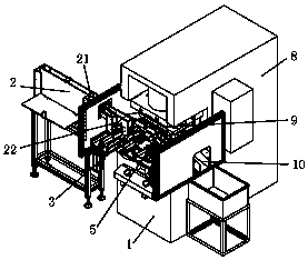
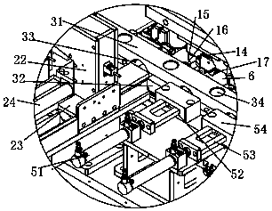
[0012] Automatic pipe punching equipment, including a frame 1, is characterized in that, the frame 1 is provided with a slide rail, and the slide rail is provided with a punching mold frame 3, and the punching mold frame 3 passes through The cylinder can slide on the slide rail. The punching mold base 3 includes an upper mold base 31 and a lower mold base 32. A pipe groove 33 is formed in the middle of the upper mold base and the lower mold base. A punching hole 34 is provided on the upper mold base; One side of the punching formwork is provided with a feeding mechanism 2 and a limit mechanism 5, and the feeding mechanism 2 includes a dual-channel conveying trough 21, and the end of the dual-channel conveying trough 21 is connected with a vertical feeding channel 22 , the bottom of the vertical feeding channel 22 is connected with a feeding trough 23, and a pushing slide plate 24 is arranged in the ...


PUM


Abstract

The invention belongs to the technical field of automatic pipe fitting punching equipment appliances, and particularly relates to automatic pipe fitting punching equipment. The automatic pipe fittingpunching equipment comprises a machine frame, wherein a sliding rail is arranged on the machine frame; a punching die frame is arranged on the sliding rail, and the punching die frame can slide on thesliding rail through an air cylinder; an upper punch is arranged on a punching machine, and the upper punch is correspondingly matched with a punching hole of the upper die frame; a discharge chute is formed in one end of the punching die frame, and a material jacking air cylinder is arranged at the side of the discharge chute; and a material jacking plate is connected to the output end of the material jacking air cylinder, and when the punching die frame with pipe fittings slides to the vicinity of the discharge chute, the material jacking air cylinder outputs to enable the material jackingplate to pushe the pipe fittings out of the punching die frame into the discharge chute. The automatic pipe fitting punching equipment has the beneficial effects that feeding, blanking, positioning and one-time punching can be completed through mechanical operation, so that the production efficiency is improved, and the yield and accuracy of products are improved at the same time.

Description

technical field [0001] The invention belongs to the technical field of automatic pipe fitting punching equipment and appliances, and in particular relates to an automatic pipe fitting punching equipment. Background technique [0002] When the current pipe fittings are punched, there are often not one punching holes for a pipe fitting, but multiple holes, and the punching positions are not on one surface, so the current common practice is to punch the pipe fittings separately. hole. That is to say, punch holes on one surface of the pipe fitting first, and after punching these holes, the next step is to punch holes on the other side of the pipe fitting. Moreover, when punching, it is all manually loaded, unloaded and positioned manually during the punching process. There are defects in this kind of operation: first, manual operation is inefficient, which can easily cause punching errors, which greatly reduces the yield of products; second, manual operation is difficult to me...

Claims


Application Information

Patent Timeline
IPC IPC(8): B21D28/28B21D43/00B21D43/02B21D28/34B21D45/02B21D37/04
CPCB21D28/28B21D28/34B21D37/04B21D43/006B21D43/027B21D45/02
Inventor 潘智平时慧丽高建中张国平汪洋曹象炜
Owner HUZHOU IRON FORCE METAL PROD
Why Eureka
Try Eureka