Electroplating product support frame structure

A support frame and product technology, applied in the electrolysis process, electrolysis components, household components, etc., can solve the problems of bumping and wearing of electroplated parts, affecting product quality and aesthetics, affecting production efficiency, etc., to improve work efficiency, ensure quality and aesthetic effect

Pending Publication Date: 2018-10-23
KUWE TECH
View PDF0 Cites 4 Cited by
  • Summary
  • Abstract
  • Description
  • Claims
  • Application Information

AI Technical Summary

Problems solved by technology

[0002] In auto parts, often many parts need to be electroplated, but most of the electroplated parts are first formed by injection molding, and then transported to the electroplating factory or sent to the next workshop for electroplating. At present, most of the electroplating methods Often, the electroplating parts are hung on the hooks and dipped into the electroplating pool, which requires the operator to install them one by one and pick them up one by one after the electroplating is completed, which seriously affects the production efficiency. At the same time, there is an inevitable disadvantage, that That is, regardless of whether the electroplating parts are sent to the electroplating factory or the next workshop after the injection molding is completed, or are transported and packaged after the electroplating is completed, it is easy to cause bumps and wear between adjacent electroplated parts during the period, affecting product quality and aesthetics

Method used


Image

  • Electroplating product support frame structure
  • Electroplating product support frame structure
  • Electroplating product support frame structure

Examples


Embodiment Construction

[0020] The specific implementation manners of the present invention will be further described in detail below in conjunction with the accompanying drawings and embodiments. The following examples are used to illustrate the present invention, but are not intended to limit the scope of the present invention.

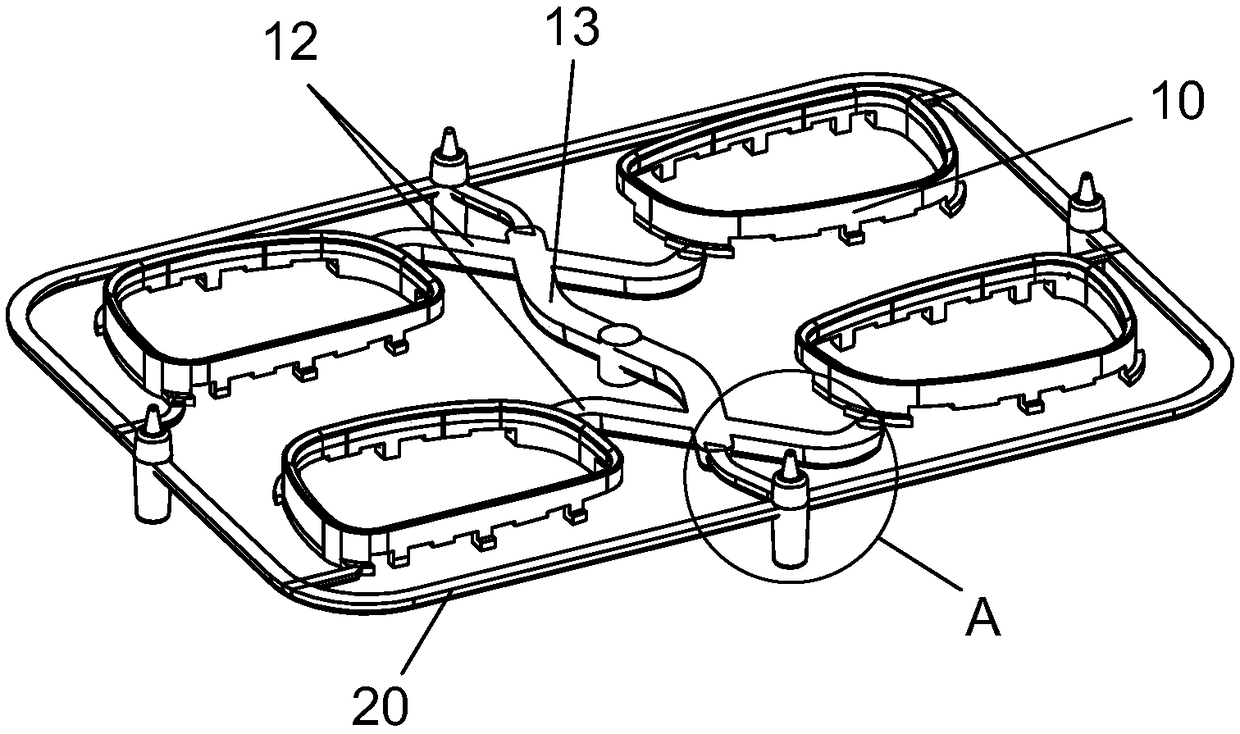
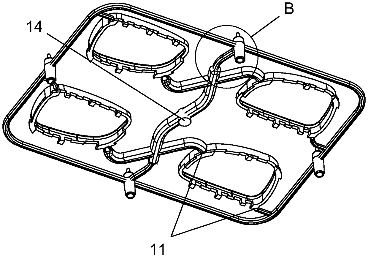
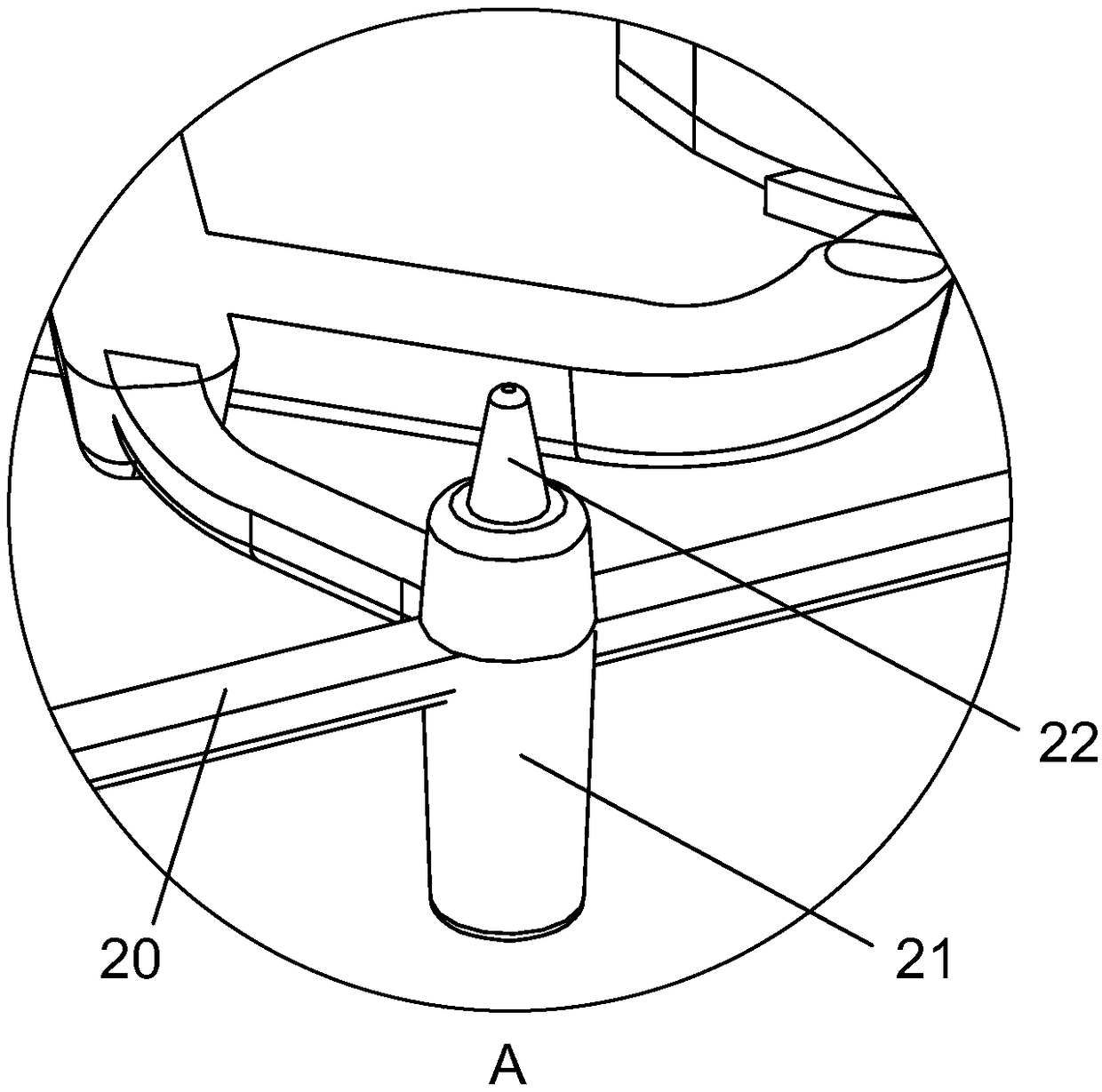
[0021] refer to Figure 1 to Figure 5 ,Such as Figure 1 to Figure 5 The shown electroplating product support frame structure includes at least one electroplating product 10, the outer edge of the electroplating product 10 is connected with a gate 11, and the gate 11 is connected with a support frame 20 arranged around the electroplating product 10, the The support frame 20 is provided with a support column 21, one end of the support column 21 is provided with a positioning protrusion 22, and the other end is provided with a positioning pit 23 that cooperates with the positioning protrusion 22 when the support columns 21 are stacked. The height is higher than the thickne...


PUM


Abstract

The invention provides an electroplating product support frame structure. The electroplating product support frame structure comprises at least one electroplating product. A sprue is connected to theouter edge of each electroplating product. Each sprue is connected with a support frame arranged around the corresponding electroplating product. and a support column is arranged on each support frame. A positioning protruding column is arranged at one end of each support column, and a positioning pit matched with the positioning protruding column is arranged at the other end of each support column when the support columns are stacked on each other. The height of each support column is higher than the thickness of each electroplating product, and the front surface and the bottom surface of each electroplating product are correspondingly arranged in the horizontal plane formed by the two end surfaces of the corresponding positioning protruding column and the corresponding positioning pit onthe corresponding supporting column. Each positioning protruding column is in a truncated cone shape, and each positioning pit is tapered and is in tapered surface fit with the corresponding positioning protruding column. The multiple support columns are arranged and uniformly arranged in the circumferential direction of each support frame. The electroplating product support frame structure is convenient to stack, the electroplating efficiency is improved, and meanwhile it can be ensured that electroplated parts are not bumped and scratched during transportation.

Description

technical field [0001] The invention relates to the field of electroplating of injection mold products, in particular to a support frame structure for electroplating products. Background technique [0002] In auto parts, often many parts need to be electroplated, but most of the electroplated parts are first formed by injection molding, and then transported to the electroplating factory or sent to the next workshop for electroplating. At present, most of the electroplating methods Often, the electroplating parts are hung on the hooks and dipped into the electroplating pool, which requires the operator to install them one by one and pick them up one by one after the electroplating is completed, which seriously affects the production efficiency. At the same time, there is an inevitable disadvantage, that That is, no matter whether the electroplating parts are sent to the electroplating factory or the next workshop after the injection molding is completed, or transported and pa...

Claims


Application Information

Patent Timeline
Patent Type & Authority Applications(China)
IPC IPC(8): B29C45/17C25D17/06B29L31/30
CPCB29C45/1769B29C2045/177B29L2031/30C25D17/06
Inventor 郑乐听陈福生刘年秋倪建周
Owner KUWE TECH
Why Eureka
Try Eureka