Hot embossing roller shaft device with spring clamping piece

A technology of hot embossing and spring parts, applied in printing, printing machines, transfer printing, etc., can solve the problems of high embossing efficiency and inconvenience, and achieve the effect of increasing heating efficiency

Active Publication Date: 2018-10-23
王致顺
View PDF8 Cites 1 Cited by
  • Summary
  • Abstract
  • Description
  • Claims
  • Application Information

AI Technical Summary

Problems solved by technology

[0002] When the existing paper product packaging is produced, it needs to go through the printing process to print the pattern. The existing printing equipment mostly uses hot embossing or ink dye technology for embossing. Since the hot embossing technology is relatively mature, and it is better than ink dye embossing The printing technology is more convenient, so hot embossing is widely used in the prior art; the hot embossing technology is to heat the embossing roller through a heating device, so that the embossing surface on the embossing roller surface expands to form a hot embossing surface with an embossing surface. template, so whether it is embossed on cardboard or wood plastic board, it will be very clear, and the embossing efficiency is very high; in the existing hot embossing roller shaft, the size and outer diameter of the embossing roller are fixed. , and most of them are equipped with only one pattern and one type of outer diameter hot embossing shaft on a set of hot embossing machines, which can only emboss products with a single pattern and a single length, which is very inconvenient

Method used


Image

  • Hot embossing roller shaft device with spring clamping piece
  • Hot embossing roller shaft device with spring clamping piece

Examples


Embodiment Construction

[0019] The present invention will be further illustrated below in conjunction with the accompanying drawings and specific embodiments. This embodiment is implemented on the premise of the technical solution of the present invention. It should be understood that these embodiments are only used to illustrate the present invention and are not intended to limit the scope of the present invention.

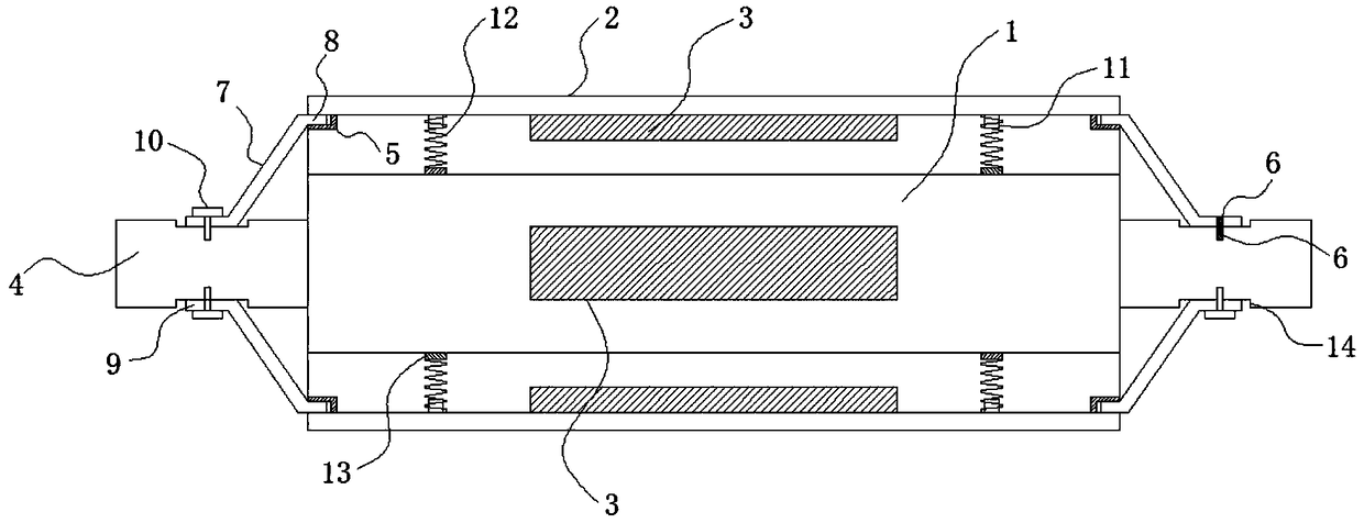
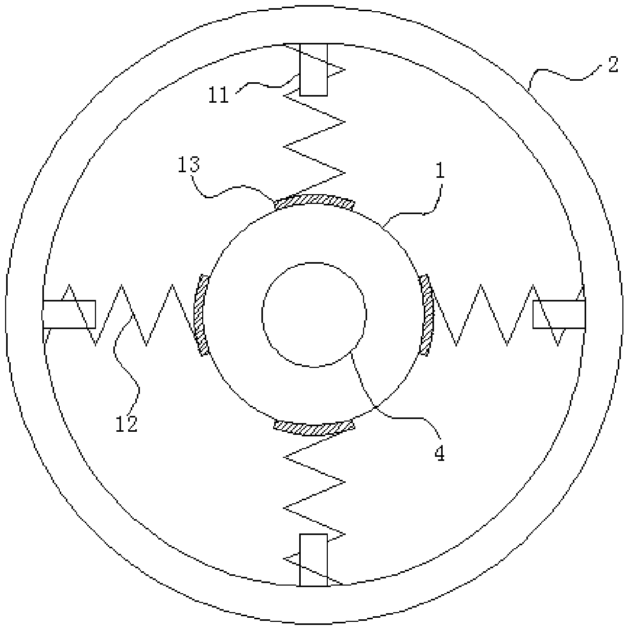
[0020] Such as figure 1 and figure 2 As shown, a hot embossing roller shaft device with a spring clip includes a hot embossing roller shaft 1 and a hot embossing roller ring 2; the inside of the hot embossing roller shaft 1 is provided with a heating device 3. The surface of the roller shaft is provided with an embossing surface, and the two ends of the hot embossing roller shaft 1 are also equipped with a transmission shaft 4, and one end of the transmission shaft 4 is correspondingly connected and installed on the transmission device, The other end is correspondingly equipped with d...


PUM


Abstract

The invention discloses a hot embossing roller shaft device with a spring clamping piece. The hot embossing roller shaft device comprises a hot embossing roller shaft and a hot embossing roller ring.A heating device is arranged in the hot embossing roller shaft, and an embossing face is arranged on the surface of the roller shaft. A transmission shaft is further correspondingly arranged at the two ends of the hot embossing roller shaft. One end of the transmission shaft is correspondingly connected to and installed on a transmission device, and the other end of the transmission shaft is correspondingly provided with a detachable bearing. The hot embossing roller ring is set to be of a straight-barrel-shaped structure, the outer surface of the hot embossing roller ring is similarly set asthe embossing face, and a heating device is similarly arranged on the inner side face of the hot embossing roller ring. According to the device, hot embossing work of different embossing patterns anddifferent embossing lengths can be finished on the same transmission shaft by replacing different embossing shafts, and the purpose of multifunctional usage is achieved.

Description

technical field [0001] The invention relates to the field of packaging and decoration printing technology and technical equipment, in particular to a thermal embossing roller shaft device with a spring clip. Background technique [0002] When the existing paper product packaging is produced, it needs to go through the printing process to print the pattern. The existing printing equipment mostly uses hot embossing or ink dye technology for embossing. Since the hot embossing technology is relatively mature, and it is better than ink dye embossing The printing technology is more convenient, so hot embossing is widely used in the prior art; the hot embossing technology is to heat the embossing roller through a heating device, so that the embossing surface on the embossing roller surface expands to form a hot embossing surface with an embossing surface. Template, so whether it is embossed on cardboard or wood plastic board, it will be very clear, and the embossing efficiency is v...

Claims


Application Information

Patent Timeline
Patent Type & Authority Applications(China)
IPC IPC(8): B41F16/00
CPCB41F16/0026
Inventor 陈爽夏宇夏军梅潘冬生
Owner 王致顺
Why Eureka
Try Eureka