Ball valve with scour-prevention valve base

An anti-scouring and valve seat technology, which is applied to valve devices, cocks including cut-off devices, engine components, etc., can solve problems such as short service life, damage to valve seats, and valve seat detachment, so as to achieve simple use and prolong service life , High reliability effect

Inactive Publication Date: 2018-10-23
李祥庆
5 Cites 4 Cited by

AI-Extracted Technical Summary

Problems solved by technology

[0002] The existing ball valve mainly includes a valve body, a valve seat, a ball and an upper valve stem. The ball is placed in the inner cavity of the valve body. It forms a seal with the outer surface of the ball. The ball is driven by the valve stem and rotates 90 degrees around the axis of the ball valve. It cooperates with the valve seat to open and close the fluid. The disadvantage is that during the proce...

Abstract

The invention relates to a ball valve with a scour-prevention valve base. The ball valve is characterized in that a positioning groove and a straight groove are formed in the bottom face of a runner,the positioning groove is of a fan arc structure with the vertical axis of the ball valve as the center line, the straight groove is formed under the horizontal axis of the ball valve, one end of thestraight groove communicates with one end of the positioning groove, the other end of the straight groove extends to a near runner opening, an adjusting device is arranged in the runner, the adjustingdevice comprises a ball clack, a compression spring, a telescopic rod, a positioning rod and an adjusting sleeve, a lower outer rod and a lower inner rod with the axes consistent with the axis of theadjusting sleeve are arranged on the lower middle portion of a valve body, the upper end of the lower outer rod is fixedly connected with the adjusting sleeve, the lower end of the lower outer rod extends out of the lower end of the valve body, the lower inner rod is arranged in the lower outer rod, the upper end of the lower inner rod is provided with a pull rod with the vertical section in an inverted right trapezoid, the pull rod extends to the upper portion of an inner cavity of the adjusting sleeve through an adjusting clamping groove, and the lower end of the lower inner rod extends outof the lower end face of the lower outer rod. The beneficial effects that the valve base is good in scour prevention, the service life is long, and safety is high are achieved.

Application Domain

Plug valves

Technology Topic

Ball valveRight trapezoid +3

Image

  • Ball valve with scour-prevention valve base

Examples

  • Experimental program(1)

Example Embodiment

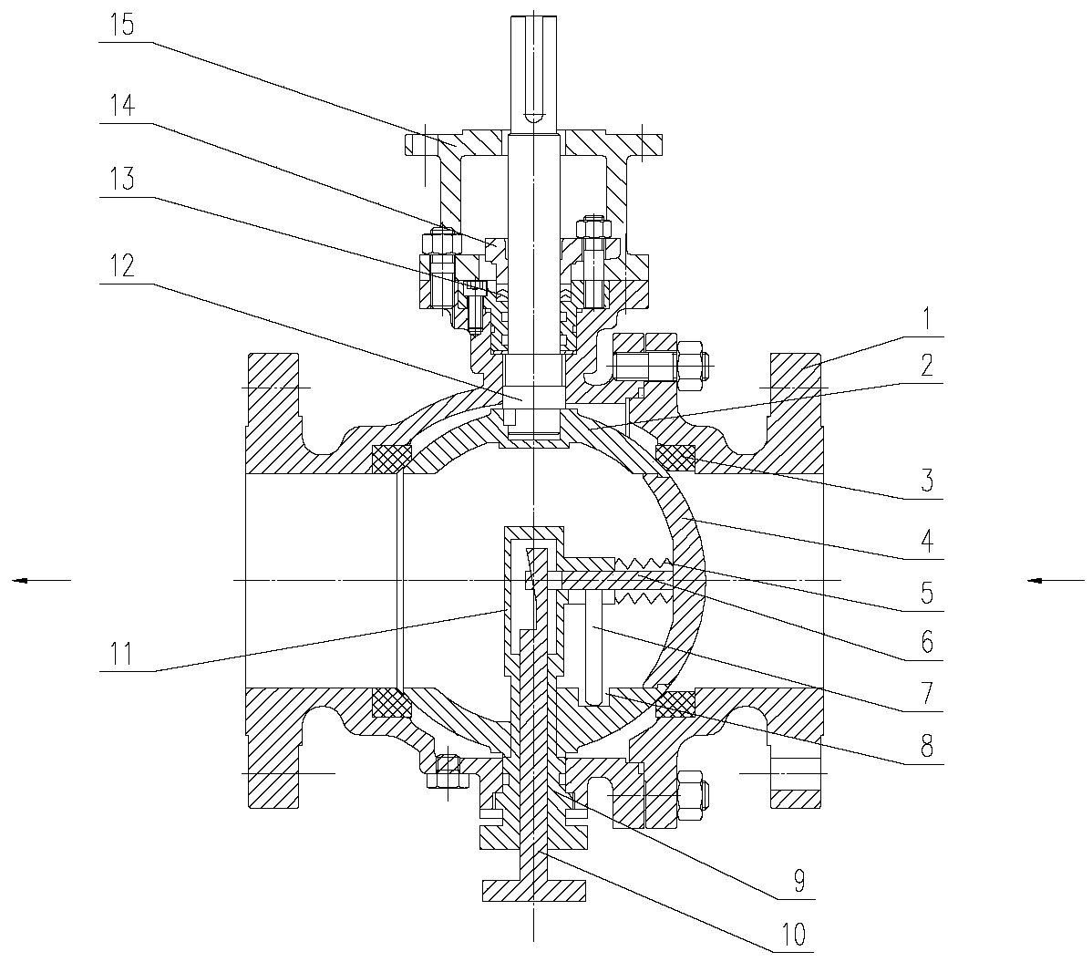
[0024] according to figure 1 It can be seen that this kind of valve seat anti-scouring ball valve includes: valve body 1, ball body 2, valve seat 3, packing 13, gland 14, connecting bracket 15 and upper valve stem 12. The upper end of valve body 1 is provided with a connecting flange And the packing groove, the packing 13 is fixedly installed at the packing groove by the gland 14, the connecting bracket 15 is installed at the connecting flange by standard fasteners, the upper end of the upper valve stem 12 is provided with a key groove connected with the external driving device, and the upper valve The lower end of the rod 12 extends through the packing groove into the inner cavity of the valve body 1 and is connected to the ball 2. The ball 2 is placed in the inner cavity of the valve body 1. The outer surface of the ball 2 is a spherical surface structure. The ball 2 is provided with an inner cavity capable of connecting with the valve body 1. The valve seat 3 is made of non-metallic plastic material and is vertically arranged in the inner cavity of the valve body 1. The valve seat 3 is provided with a seat sealing surface that forms a seal with the outer surface of the sphere 2, and the sphere 2 is formed by the upper stem 12 drives and rotates 90 degrees around the vertical axis of the ball valve to open or close the ball valve. The bottom surface of the flow channel is provided with a positioning groove 8 and a straight groove. The positioning groove 8 forms a fan arc with the vertical axis of the ball valve as the center line. The straight groove is arranged directly below the horizontal axis of the ball valve. One end of the straight groove communicates with one end of the positioning groove 8, and the other end of the straight groove extends to the nearby flow passage opening; the flow passage is provided with an adjusting device, the The adjusting device includes a ball flap 4, a compression spring 5, a telescopic rod 6, a positioning rod 7, and an adjusting sleeve 11. The adjusting sleeve 11 has an inverted barrel structure and is vertically arranged in the flow channel with the vertical axis of the ball valve as the center line. One end of the ball valve 4 is provided with a spherical surface consistent with the radius of the outer surface of the ball 2, the outer circle of the ball valve 4 is consistent with the size of the diameter of the flow passage, the telescopic rod 6 is arranged horizontally, and one end of the telescopic rod 6 is fixedly arranged on the ball valve 4. On one end, the other end of the telescopic rod 6 is provided with an adjusting slot, which extends into the adjusting sleeve 11. The positioning rod 7 is arranged vertically, the upper end of the positioning rod 7 is fixed on the telescopic rod 6, and the lower end of the positioning rod 7 extends into the positioning groove In 8, the compression spring 5 is transversely arranged between the ball flap 4 and the adjusting sleeve 11; in the lower part of the valve body 1 is provided a lower outer rod 9 and a lower inner rod 10 whose axis is consistent with the axis of the adjusting sleeve 11. The lower outer rod 9 The upper end is fixedly connected with the adjusting sleeve 11, the lower end of the lower outer rod 9 extends out of the lower end of the valve body 1, the lower inner rod 10 is placed inside the lower outer rod 9, and the upper end of the lower inner rod 10 is provided with a vertical cross-section of an inverted right-angle trapezoid The pull rod extends to the upper part of the inner cavity of the adjusting sleeve 11 through the adjusting slot, the lower end of the lower inner rod 10 extends out of the lower end surface of the lower outer rod 9, and the lower end of the lower inner rod 10 is provided with a grip block.
[0025] The use method of this kind of seat anti-scouring ball valve:
[0026] The use method of closing this kind of seat anti-scouring ball valve is as follows:
[0027] a. Rotate the lower outer rod to drive the adjusting sleeve, telescopic rod, positioning rod, compression spring and ball flap to rotate along the shape of the positioning groove.
[0028] b. When the positioning rod reaches the straight groove position, the ball valve moves along the straight groove to the flow passage under the push of the compression spring, and finally the ball valve
[0029] Staying at the mouth of the flow passage, the outer surface of the ball valve and the outer surface of the sphere form a whole,
[0030] c. Then turn the upper valve stem into a 90-degree rotation to close the seat anti-scouring ball valve; at this time the valve is closed
[0031] In the process of closing, the sealing surface of the valve seat is always close to the surface of the ball or the valve seat. The medium on the inlet side of the ball valve cannot enter the outlet side through the surface of the ball or the valve seat, and the medium will not flush the sealing surface of the valve seat.
[0032] The use method of opening this kind of seat anti-scouring ball valve is as follows:
[0033] a. First turn the upper valve stem into a 90-degree rotation, so that the flow passage is aligned with the inlet of the ball valve,
[0034] b. Pull down the inner rod again, and the telescopic rod will drive the positioning rod out of the straight groove under the action of the pull rod with an inverted right-angle trapezoid in cross section.
[0035] When driving the ball valve out of the flow passage,
[0036] c. Rotate the lower outer rod again to drive the ball flap, compression spring, telescopic rod, and positioning rod to return to the original position along the positioning groove. At this time, the valve opens.
[0037] During the opening process, the sealing surface of the valve seat is always close to the surface of the ball or the valve seat. The medium on the inlet side of the ball valve cannot enter the outlet side through the surface of the ball or the valve, and the medium will not wash the sealing surface of the valve seat.
[0038] In summary, the above are only preferred embodiments of the present invention, and are not used to limit the protection scope of the present invention. Any modification, equivalent replacement, improvement, etc., made within the spirit and principle of the present invention shall be included in the protection scope of the present invention.

PUM

no PUM

Description & Claims & Application Information

We can also present the details of the Description, Claims and Application information to help users get a comprehensive understanding of the technical details of the patent, such as background art, summary of invention, brief description of drawings, description of embodiments, and other original content. On the other hand, users can also determine the specific scope of protection of the technology through the list of claims; as well as understand the changes in the life cycle of the technology with the presentation of the patent timeline. Login to view more.

Similar technology patents

Glomerocryst cubic boron nitride composite sheet and preparation method for same

ActiveCN103158287AExtended service lifeIncreased depth of cut
Owner:ZHENGZHOU BERLT HARD MATERIALS

Sleep assistance mattress

ActiveCN106842979AReduce data processing pressureExtended service life
Owner:DONGGUAN UNIV OF TECH

Application of epoxy cardanol as bio-based hindered phenolic antioxidant

InactiveCN105219458AGood antioxidant propertiesExtended service life
Owner:INST OF CHEM IND OF FOREST PROD CHINESE ACAD OF FORESTRY

Classification and recommendation of technical efficacy words

  • Extended service life
  • improve security

Fracturing manifold quick connecting device

Owner:YANTAI JEREH PETROLEUM EQUIP & TECH

Modified asphalt composition with creeping characteristic and preparation method thereof

InactiveCN102020859Aavoid rapid agingExtended service life
Owner:ZHEJIANG WOPUMAN HIGH NEW MATERIALS

Pesticide micro-capsule granules and preparation method thereof

InactiveCN102100229Alow toxicityimprove security
Owner:联合国南通农药剂型开发中心 +1

Method for achieving user authentication by utilizing camera

InactiveCN103678984Aimprove securityGuaranteed picture quality
Owner:湖北微模式科技发展有限公司
Why Eureka
Try Eureka