
Integrated flow gas and air equipment inspection hole door

An equipment inspection and integrated technology, which is applied to lighting and heating equipment, combustion product treatment, combustion methods, etc., can solve the problems of low reliability, many fastening bolts, and heavy structure, so as to improve the reliability of use, The effect of improving welding performance and avoiding equipment downtime

Pending Publication Date: 2018-10-23
满洲里达赉湖热电有限公司
View PDF0 Cites 0 Cited by
  • Summary
  • Abstract
  • Description
  • Claims
  • Application Information

AI Technical Summary

Problems solved by technology

[0002] As we all know, the purpose of installing inspection holes is the internal inspection of equipment. The inspection holes used in the production site are generally steel plate or casting inspection holes. Such inspection holes have problems such as poor welding performance, heavy structure and many fastening bolts, and cannot be installed in Outside the equipment casing, the sealing surface cannot be installed with packing, and when the inspection hole is installed on the smoke and air system, the system needs to be shut down for welding and installation purposes, resulting in low reliability

Method used


Image

  • Integrated flow gas and air equipment inspection hole door
  • Integrated flow gas and air equipment inspection hole door

Examples


Embodiment Construction

[0011] The specific implementation manners of the present invention will be further described in detail below in conjunction with the accompanying drawings and embodiments. The following examples are used to illustrate the present invention, but are not intended to limit the scope of the present invention.

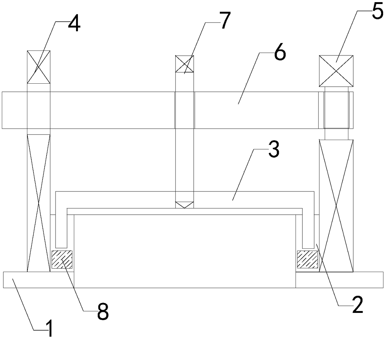
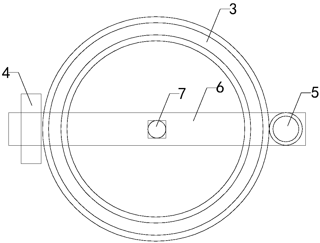
[0012] like Figure 1 to Figure 2 As shown, the integrated flue gas equipment inspection hole door of the present invention includes a casing 1, an inspection hole seat 2, an inspection hole cover 3, a support plate 4, a pole 5, a cover plate support beam 6 and a cover plate top wire 7, The inspection hole seat is set on the casing, the bottom ends of the support plate and the support rod are connected with the casing, and the support plate and the support rod are respectively located on the left and right sides of the inspection hole seat, and the inspection hole cover matches the inspection hole seat , and a filler 8 is arranged between the inspection hole cover and the...


PUM


Abstract

The invention relates to the technical field of inspection hole door accessory devices, in particular to an integrated flow gas and air equipment inspection hole door. The integrated flow gas and airequipment inspection hole door can enhance welding performance, has portable structure and tight sealing, and can be mounted during equipment operating, the equipment shut-down can be avoided, the application reliability can be enhanced. The integrated flow gas and air equipment inspection hole door comprises a shell, inspection hole seats, an inspection hole cover, a support plate, a support bar,a cover plate support beam and a cover plate jackscrew. The inspection hole seats are arranged on the shell, the bottom end of the support plate and the bottom end of the support bar are connected with the shell. In addition, the support plate and the support bar are correspondingly located on the left and right sides of the inspection hole seats, and padding is arranged between the inspection hole cover and the inspection hole seats. A clamping groove is formed in the top of the front of the support bar. The right end of the cover plate support beam is connected with the top of the support bar in a rotating mode. The left end of the cover plate support beam is mounted in the clamping groove in a clamping mode, and a threaded hole penetrating through up and down is formed in the middle ofthe cover plate support beam. The bottom end of the cover plate jackscrew is connected with the top end of the cover plate support beam through thread penetrating through the threaded hole and attached to the middle of the top end of the inspection hole cover.

Description

technical field [0001] The invention relates to the technical field of inspection hole accessories, in particular to an integrated inspection hole door for smoke and wind equipment. Background technique [0002] As we all know, the purpose of installing inspection holes is the internal inspection of equipment. The inspection holes used in the production site are generally steel plate or casting inspection holes. Such inspection holes have problems such as poor welding performance, heavy structure and many fastening bolts, and cannot be installed in Outside the equipment casing, the sealing surface cannot be installed with packing, and when the inspection hole is installed on the flue gas system, the system needs to be shut down for the purpose of welding and installation, resulting in low reliability. SUMMARY OF THE INVENTION [0003] In order to solve the above technical problems, the present invention provides an integrated smoke and air equipment inspection hole door wi...

Claims


Application Information

Patent Timeline
IPC IPC(8): F23J13/08
CPCF23J13/08
Inventor 于龙韩双江杨雪山
Owner 满洲里达赉湖热电有限公司
Learn More