A carrier for testing the lateral radar cross section of the antenna

A radar scattering and cross-sectional area technology, which is applied in the field of communication, can solve problems such as the inability to measure the antenna scattering cross-sectional area, and achieve the effect of small equivalent signal receiving area and reduced interference

Active Publication Date: 2020-03-10
BEIJING INST OF ENVIRONMENTAL FEATURES
View PDF4 Cites 0 Cited by
  • Summary
  • Abstract
  • Description
  • Claims
  • Application Information

AI Technical Summary

Problems solved by technology

[0005] The technical problem to be solved by the present invention is to provide a solution to the problem that the lateral radar scattering cross-sectional area of ​​the antenna cannot be accurately measured in view of the defects in the prior art.

Method used


Image

  • A carrier for testing the lateral radar cross section of the antenna
  • A carrier for testing the lateral radar cross section of the antenna
  • A carrier for testing the lateral radar cross section of the antenna

Examples


Embodiment 1

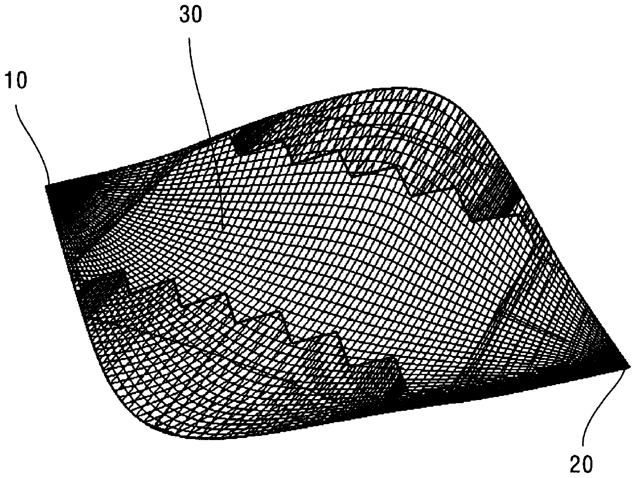
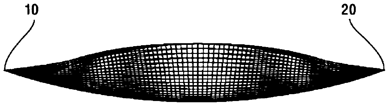
[0051] Such as figure 1 As shown, an embodiment of the present invention provides a carrier for testing the lateral radar cross-sectional area of ​​the antenna, and the shape of the carrier is a shuttle-like structure with sharp corners at the left end 10 and right end 20;

[0052] The top of the carrier is provided with an antenna installation groove 30, and the distance between the installation groove 30 and the left end 10 and the right end 20 is equal;

[0053] The antenna under test can be installed in the installation slot 30 , and the left side of the antenna under test is opposite to the left end 10 , and the right side of the antenna under test is opposite to the right end 20 .

[0054]When in use, the antenna to be tested can be installed in the mounting groove of the carrier so that the left side of the antenna to be tested is opposite to the left end of the carrier, and the right side of the antenna to be tested is opposite to the right end. The antenna installed ...

Embodiment 2

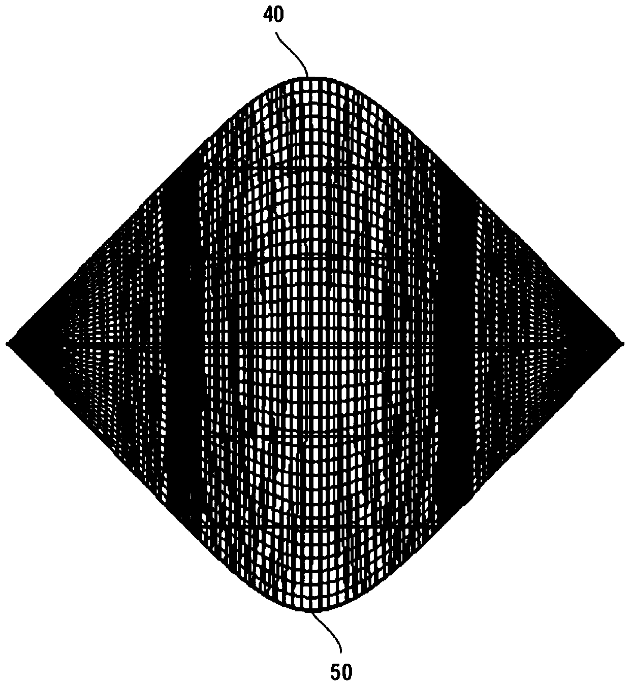
[0056] Such as figure 2 As shown, the second embodiment is basically the same as the first embodiment, and the similarities will not be repeated. The difference lies in:

[0057] The bottom view of the carrier is rhombus-like;

[0058] Both the upper corner 40 and the lower corner 50 of the rhombus are rounded.

[0059] In the second embodiment, the shape of the carrier is a shuttle-like structure with sharp corners at the left end and the right end, and the bottom view of the carrier is a rhombus-like shape, and the upper and lower corners of the rhombus-like shape are rounded, so when When the test signal is sent from the left or right side of the carrier to the antenna under test, the equivalent signal receiving area of ​​the carrier relative to the test signal is relatively small, further reducing the interference caused by the scattering field of the carrier itself to the scattering field of the antenna under test.

Embodiment 3

[0061] The third embodiment is basically the same as the second embodiment, and the similarities will not be repeated. The difference is that the carrier has a symmetrical structure with a designated dividing plane, wherein the designated dividing plane is perpendicular to the left end 10 and the The connecting line between the right end portions 20, and the center of the carrier is located on the dividing plane. In this way, it can be ensured that no matter whether the test signal is sent from the left side or the right side of the carrier to the antenna mounted on the carrier to test the lateral radar cross-sectional area of ​​the antenna to be tested, the test effect and test result are the same.


PUM


Abstract

The invention relates to a carrier, the shape of the carrier is a shuttle-like structure with sharp corners at the left end and the right end; the top of the carrier is provided with a mounting groove for mounting an antenna, and the mounting groove is respectively connected to the The distance between the left end and the right end is equal; the antenna to be tested can be installed in the installation groove, and the left side of the antenna to be tested is opposite to the left end, and the right side of the antenna to be tested is The face is opposite to the right end. The technical solution provided by the present invention transmits test signals from the left or right side of the carrier to the antenna installed on the carrier, so that when testing the lateral radar cross-sectional area of ​​the antenna, the side of the antenna can be more accurately measured. Radar scatter cross-section.

Description

technical field [0001] The invention relates to the field of communication technology, in particular to a carrier for testing the lateral radar scattering cross-sectional area of ​​an antenna. Background technique [0002] When measuring the radar scattering characteristics of an antenna, it is usually necessary to configure a corresponding low-scattering carrier for the antenna. [0003] At present, the existing low-scattering carrier is usually designed for the head-to-head test index of the antenna. When the antenna to be tested is installed on the existing low-scattering carrier to test the antenna's side radar The scattering field of the low-scattering carrier itself will have a great impact on the scattering field of the antenna under test, and it is impossible to accurately measure the lateral radar cross-sectional area of ​​the antenna. [0004] Therefore, in view of the above deficiencies, it is necessary to provide a solution to the problem that the lateral radar ...

Claims


Application Information

Patent Timeline
Patent Type & Authority Patents(China)
IPC IPC(8): G01S7/40
CPCG01S7/4004
Inventor 赵轶伦汪勇峰戚开南
Owner BEIJING INST OF ENVIRONMENTAL FEATURES
Why Eureka
Try Eureka