Method for measuring and determining paleocurrent direction
A technology of electrical imaging and well logging, applied in the direction of electrical/magnetic detection for well logging records, etc., can solve the problems of unmentioned technical solutions for measuring paleoflow direction, uncertainty of analysis results, and poor reliability, etc. Achieve the effects of saving manpower and financial resources, good measurement accuracy, and fast processing speed
- Summary
- Abstract
- Description
- Claims
- Application Information
AI Technical Summary
Problems solved by technology
Method used
Image

Examples
Embodiment 1
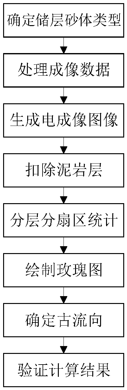
[0038] The method for determining the paleo-flow direction of a channel-type sand body reservoir by using electrical imaging logging data involved in this embodiment, the specific technological steps for its realization are as follows:
[0039] (1) Determine the type of reservoir sand body:
[0040] In this example, according to the relevant geological data, the area where the well to be tested is located in the north-central part of the Yishan slope in the Ordos Basin. The application conditions of the method of the present invention can determine the paleo-flow direction through imaging logging data;
[0041] (2) Processing imaging data:
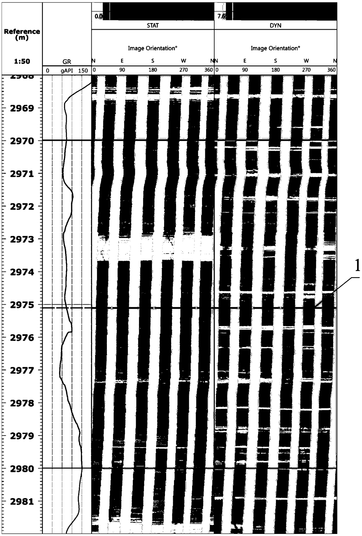
[0042] Obtain the original electrical imaging logging data of the measured well, and first correct the measured azimuth curve; the magnetic declination at the point where the well is located is -2.63°, and the longitude difference between the calculation point and the central meridian is 1.88° , the latitude of the calculation point is 3...
Embodiment 2
[0063] This embodiment relates to a method for verifying the measurement results of Example 1. First, the well contains coring data, figure 2 The winning number 1 is the coring position. The full-diameter rock core is used to make the cake-shaped rock sample and the standard plunger sample respectively, and then the orientation of the rock sample is determined by remanence redirection; the cake-shaped rock sample is divided into 24 sectors, each Cut a flat section on the side of each sector, measure and calculate the conductivity of each group of relative sectors, and draw the results in polar coordinates, as shown in Figure 4 Shown in the middle mark 7; use the standard plunger sample to measure the core permeability, and draw the measurement result in polar coordinates according to its orientation, as shown in Figure 5 Shown in number 8; by Figure 5 The determined maximum conductivity direction and the main direction of permeability are 112.5° (or 292.5°). Comparing the...
PUM
 Abstract
Description
Claims
Application Information