Methods and systems for additive manufacturing

A technology of three-dimensional manufacturing and controller, applied in the field of additive manufacturing, which can solve the problems that physical principles are not applicable to metal-based systems

Inactive Publication Date: 2018-10-23
DESKTOP METAL INC
View PDF3 Cites 4 Cited by
  • Summary
  • Abstract
  • Description
  • Claims
  • Application Information

AI Technical Summary

Problems solved by technology

While these polymer-based technologies have changed and improved over the years, the physical principles tha

Method used


Image

  • Methods and systems for additive manufacturing
  • Methods and systems for additive manufacturing
  • Methods and systems for additive manufacturing

Examples


Embodiment Construction

[0067] Embodiments will now be described more fully hereinafter with reference to the accompanying drawings, in which preferred embodiments are shown. However, the foregoing may be embodied in many different forms and should not be construed as limited to the illustrated embodiments set forth herein.

[0068] All documents mentioned herein are incorporated by reference in their entirety. Unless expressly stated otherwise or clear from context, references to singular items shall be understood to include plural items and vice versa. Unless otherwise stated or clear from context, grammatical conjunctions are intended to express any and all inflectional and connecting combinations of connected clauses, sentences, words, etc. Thus, the term "or" should generally be read to mean "and / or" and the like.

[0069] Recitations of ranges of values ​​herein are not intended to be limiting, but instead refer individually to any and all values ​​falling within that range, unless otherwise ...


PUM


Abstract

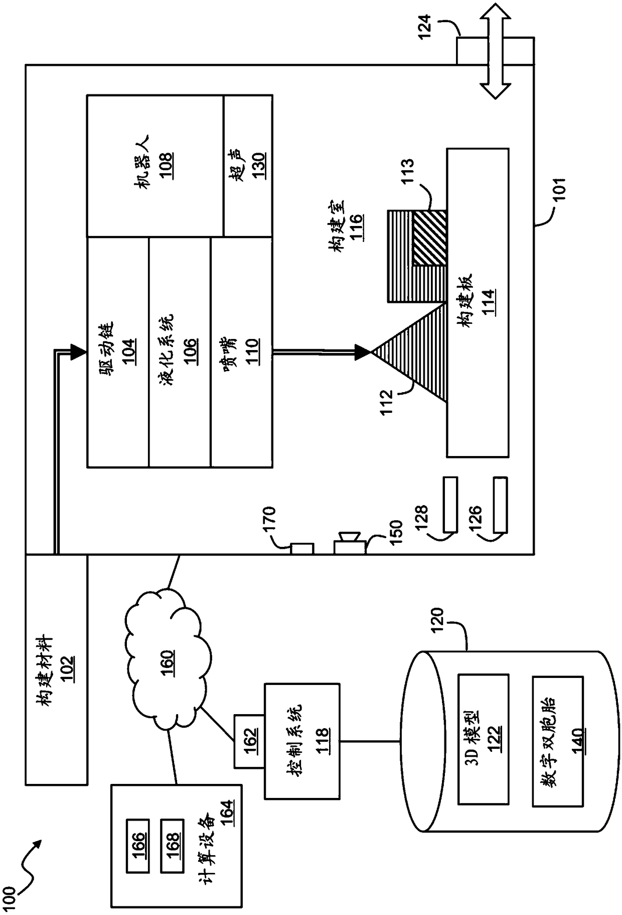
In an aspect, a printer fabricates an object from a computerized model using a fused filament fabrication process and a metallic build material. An ultrasonic vibrator is incorporated into the printerto improve the printing process, e.g., by disrupting a passivation layer on the deposited material to improve interlayer bonding, and to prevent adhesion of the metallic build material to a nozzle and other printer components.

Description

[0001] Cross References to Related Applications [0002] This application claims U.S. Provisional Application No. 62 / 268458, filed December 16, 2015, U.S. Provisional Application No. 62 / 303310, filed March 3, 2016, and U.S. Provisional Application No. 62, filed April 14, 2016 Priority of / 322760. The entire contents of each of the above applications are hereby incorporated by reference. [0003] This application is related to commonly-owned US Patent Application Serial No. 15 / 059256, filed March 2, 2016. This application is also related to the following commonly-owned U.S. Patent Applications filed on the same date herewith: Attorney Docket No. DESK-0003-P01, titled "Metal Printer With Vibrating Ultrasonic Nozzle"; Attorney Docket No. DESK-0003-P02, titled for "Joule Heating for Improving Interlaminar Bonding in Fused Filament Fabrication of Metallic Objects"; Attorney Docket No. DESK-0003-P03, entitled "Bulk Metallic Glass Printer with Shear Engine in Feed Path" ; Attorney's...

Claims


Application Information

Patent Timeline
IPC IPC(8): B29C47/04B29C47/06B33Y30/00
CPCB22F3/20B22F3/227B22F2999/00C22C2200/02B33Y10/00B33Y30/00B33Y50/02Y02P10/25G05B2219/49007G05B19/4099B22F10/30B22F12/57B22F10/18B22F10/43B22F12/10B22F12/55B22F12/90B22F12/53B22F2202/01B29C64/40B29C64/106B22F3/115B22F3/24B22F9/007B22F2003/247B22F2203/11B29K2101/12B29K2105/16B29K2505/00B29K2509/08
Inventor C.A.舒赫J.S.梅尔伯格R.富洛普Y-M.张A.J.哈特J.施罗尔斯M.D.弗明斯基N.M.米库洛维茨J.Y.希姆R.R.丰塔纳M.A.吉布森R.秦E.M.萨克斯
Owner DESKTOP METAL INC
Why Eureka
Try Eureka