Liquid-cooled fused filament fabrication nozzle

Active Publication Date: 2019-09-17
AREVO INC
View PDF4 Cites 1 Cited by
  • Summary
  • Abstract
  • Description
  • Claims
  • Application Information

AI Technical Summary

Problems solved by technology

The ability to provide this critical temperature control becomes particularly difficult when high-temperature polymers such as

Method used


Image

  • Liquid-cooled fused filament fabrication nozzle
  • Liquid-cooled fused filament fabrication nozzle
  • Liquid-cooled fused filament fabrication nozzle

Examples


Embodiment Construction

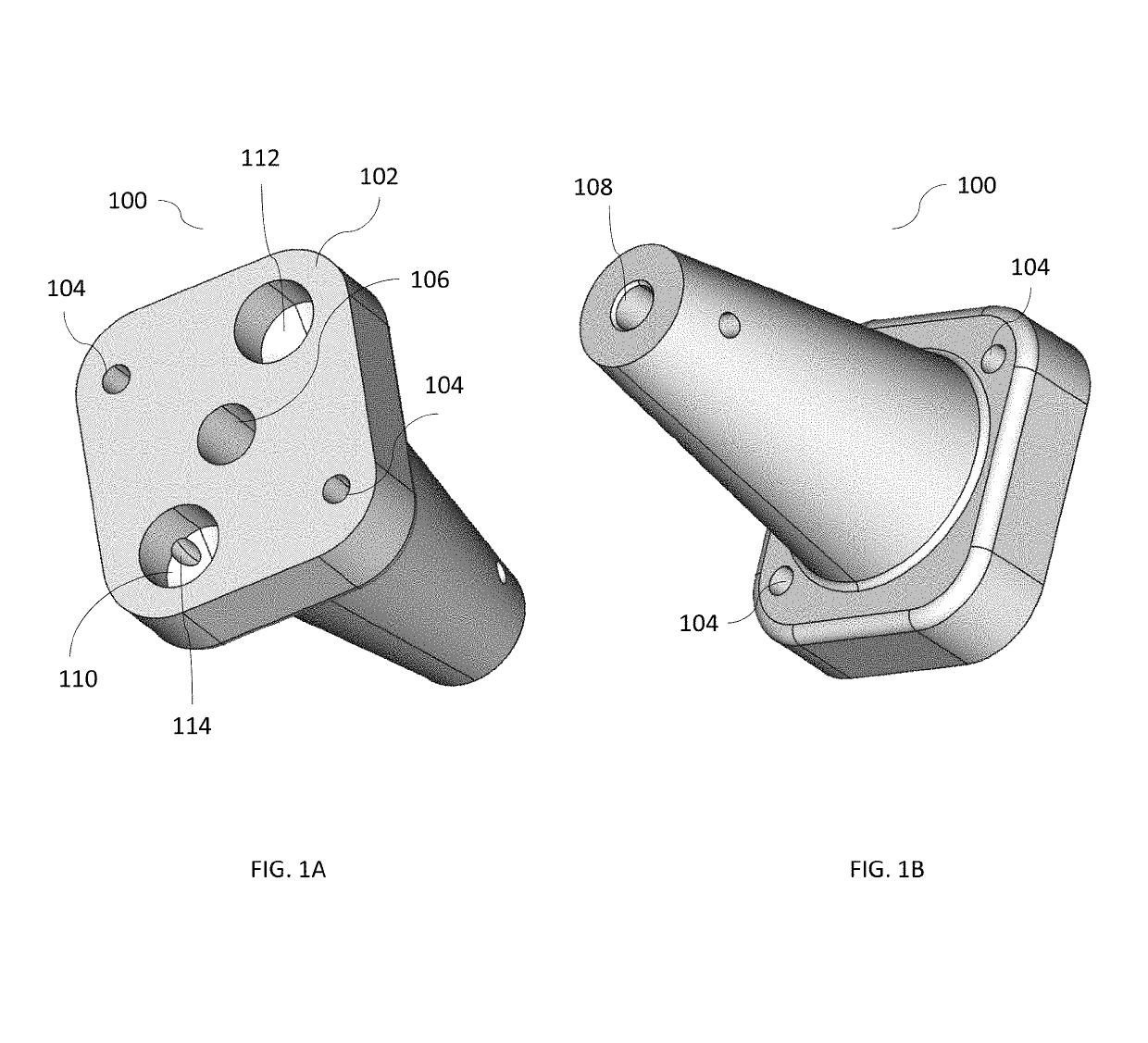
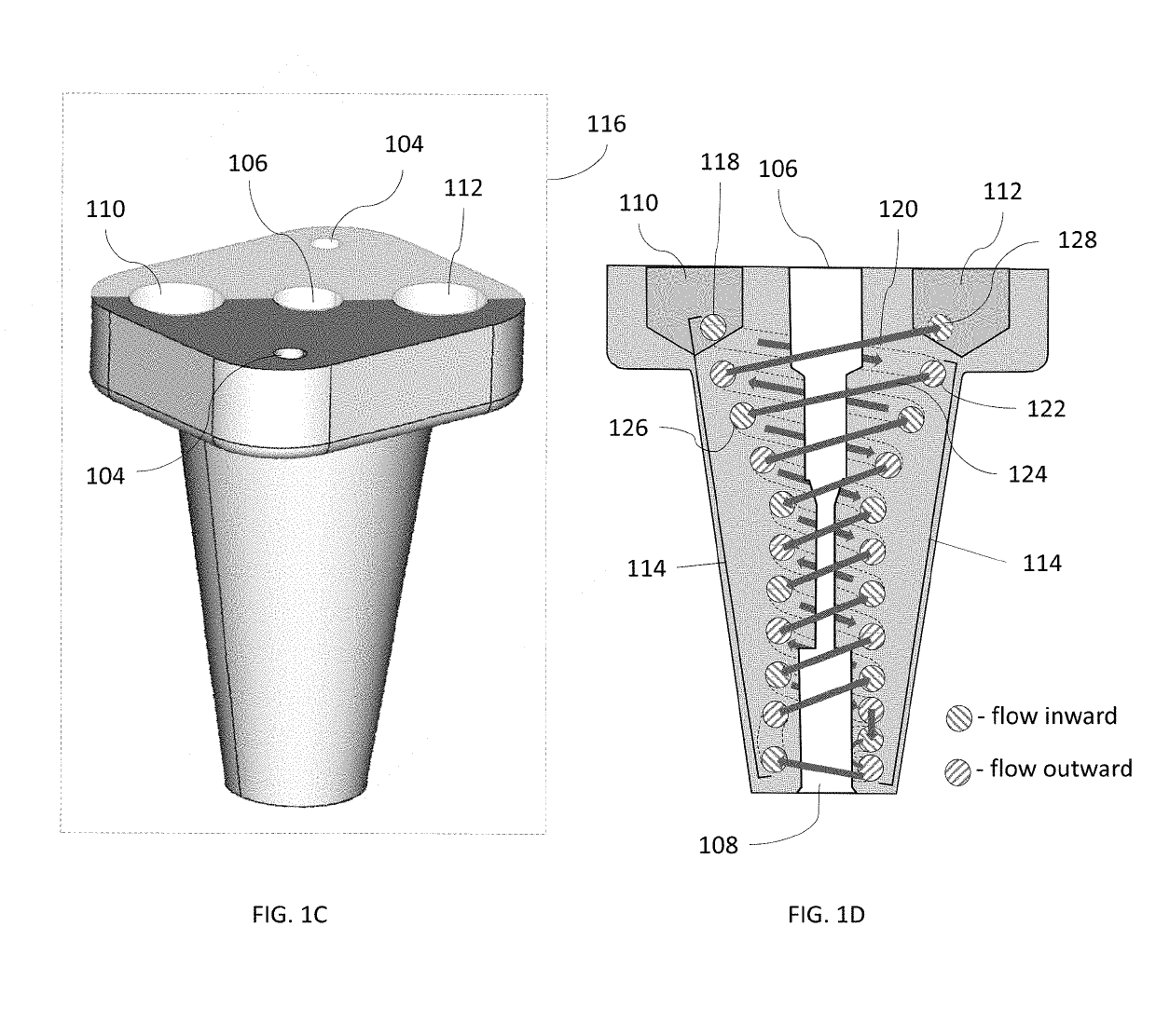
[0017]FIGS. 1A, 1B, 1C and 1D depict an exemplary embodiment of an extrusion nozzle manifold according to one embodiment of the present disclosure. As illustrated, the manifold 100 has a planar upper surface 102 facilitating attachment to an extrusion system. Mounting holes 104 are provided to accept fasteners (not illustrated) for securing the manifold to the extrusion system. A central filament channel 106 is located within the manifold. The top of central filament channel 106 is adapted to accept the input of a filament, and nozzle aperture 108 is formed at its bottom.

[0018]In a preferred embodiment of the invention, extrusion nozzle manifold 100 is manufactured from powdered aluminum using a direct metal laser sintering (“DMLS”) 3D printing process. Although aluminum powder was utilized in a preferred embodiment, several other metals such as stainless steel and titanium, as well as nickel and chromium alloys, can also be utilized in the DMLS process. The particular material empl...


PUM

PropertyMeasurementUnit
Lengthaaaaaaaaaa
Electrical conductoraaaaaaaaaa
Surface areaaaaaaaaaaa

Abstract

The present invention provides an integral cooling system within an FFF nozzle manifold. The system includes a cooling reservoir formed within the body of the nozzle manifold, adapted to circulate a cooling liquid around the filament chamber and nozzle orifice. The coolant channel is situated to be in close physical proximity to the chamber and orifice, and to be thermally coupled to both via the body of the nozzle manifold. In addition, the interior of the cooling chamber is constructed so as to maximize the available surface area within a given cross-sectional geometry, thereby promoting increase heat transfer between the nozzle manifold and the cooling liquid.

Description

FIELD OF THE INVENTION[0001]The present invention relates generally to fused filament fabrication, and more specifically to the cooling of nozzles employed in such fabrication processes.BACKGROUND OF THE INVENTION[0002]The additive manufacturing process is widely known as “3D printing.” Numerous 3D-printing methodologies have been described in prior art, the most common being solid-laser sintering (SLS), stereolithography (SLA), and extrusion-based 3D printing or fused filament fabrication (FFF).[0003]All of these methods involve depositing a thin layer of thermoplastic or thermoset materials. In FFF, thin strands of material (referred to herein as “extrudate”) are deposited from a deposition nozzle onto a build surface. As the filament moves through the FFF system, it undergoes mechanical, chemical, and thermal changes. Deposition proceeds in a controlled pattern on the build surface to construct a 3D object.[0004]In operation of an FFF system, a filament of material is fed into a ...

Claims


Application Information

Patent Timeline
IPC IPC(8): F28D15/00F28F7/02F28D7/00B33Y70/00B33Y80/00B33Y10/00B22F3/105
CPCF28D7/0008F28F7/02B33Y70/00B33Y80/00B33Y10/00F28F2255/18B22F2301/052B22F3/1055B22F5/10B29C48/30B22F2005/004B29C48/05B29C48/266B29C48/87B29C48/3001B29C64/209B29C64/118B29C2035/1625B33Y30/00Y02P10/25B22F10/28B22F12/20B22F12/53
Inventor SUNDEN, ERIK
Owner AREVO INC
Why Eureka
Try Eureka