Hardware product spraying device convenient to use

A spraying device and hardware technology, applied in the direction of spraying device, liquid spraying device, device for coating liquid on the surface, etc., can solve the problems of low work efficiency, simple function, inconvenient use, etc., achieve convenient operation and reduce expenses , the effect of reducing waste

Inactive Publication Date: 2018-10-26
佛山市顺德区恒恩裕电器实业有限公司
9 Cites 21 Cited by

AI-Extracted Technical Summary

Problems solved by technology

[0003] When hardware products are in use, due to the different use environments, the hardware products will be sprayed, but there are still some deficiencies in the exist...

Abstract

The invention discloses a hardware product spraying device convenient to use. The hardware product spraying device comprises a main body. The left side of the top of the inner wall of the main body isfixedly connected with a hydraulic telescopic rod. The bottom end of the hydraulic telescopic rod is fixedly connected with a lifting plate. The bottom of the lifting plate is fixedly connected withtwo high-pressure spraying heads. The left side of the top of the main body is fixedly connected with a spraying material box. The bottom of the spraying material box communicates with two hoses. Thebottom ends of the two hoses penetrate through the main body and extend into the main body. The ends, in the main body, of the two hoses communicate with the two high-pressure spraying heads correspondingly. The right side of the top of the main body is fixedly connected with a lifting device. The bottom of the lifting device is fixedly connected with a connecting rod. The top end of the connecting rod penetrates through the main body and extends into the main body. The hardware product spraying device convenient to use is simple in structure, wide in using range, easy to use and convenient tooperate and has the spraying and drying effects simultaneously, meanwhile, spraying paint is recycled, waste is reduced, and unnecessary expenses are reduced.

Application Domain

Technology Topic

Image

  • Hardware product spraying device convenient to use
  • Hardware product spraying device convenient to use

Examples

  • Experimental program(1)

Example Embodiment

[0016] The technical solutions in the embodiments of the present invention will be clearly and completely described below in conjunction with the accompanying drawings in the embodiments of the present invention. Obviously, the described embodiments are only a part of the embodiments of the present invention, rather than all the embodiments. Based on the embodiments of the present invention, all other embodiments obtained by those of ordinary skill in the art without creative work shall fall within the protection scope of the present invention.
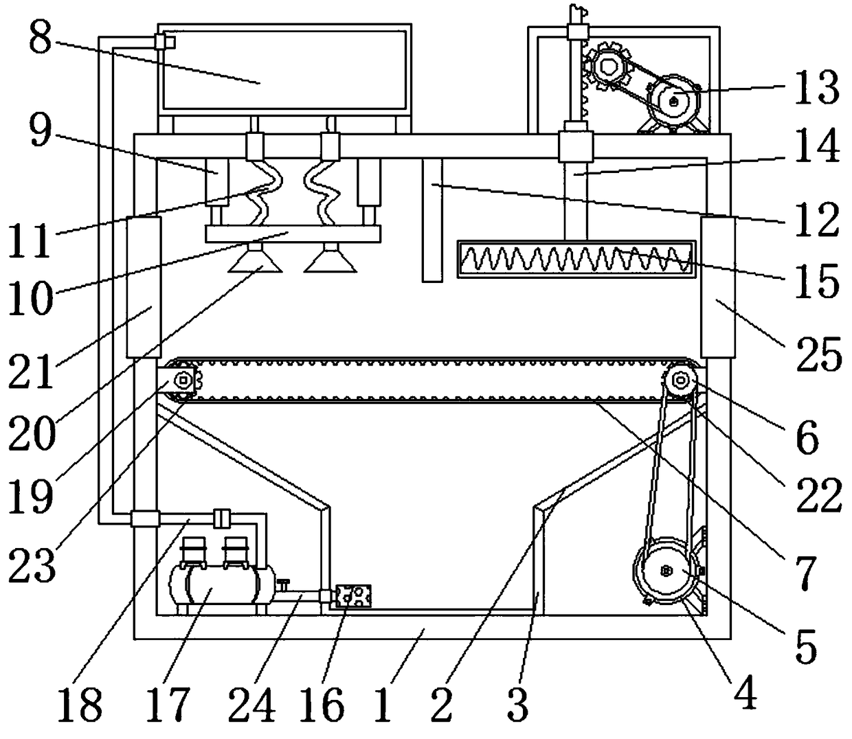
[0017] See Figure 1~2 In the embodiment of the present invention, an easy-to-use hardware spraying device includes a main body 1. A hydraulic telescopic rod 9 is fixedly connected to the left side of the top of the inner wall of the main body 1, and the hydraulic telescopic rod 9 cooperates with the lifting plate 10 to control the height during spraying. Metal products of different sizes can be sprayed, and the scope of application is wider. The bottom end of the hydraulic telescopic rod 9 is fixedly connected with a lifting plate 10, and the bottom of the lifting plate 10 is fixedly connected with two high-pressure nozzles 20. The high-pressure nozzles 20 make the spray paint evenly sprayed. Spraying more fully on the surface of the hardware. The spray box 8 is fixedly connected to the left side of the top of the main body 1. The bottom of the spray box 8 is connected with two hoses 11, and the bottom ends of the two hoses 11 penetrate the main body 1. And extend to the inside of the main body 1, the ends of the two hoses 11 located inside the main body 1 are respectively connected to the two high-pressure nozzles 20, the right side of the top of the main body 1 is fixedly connected with a lifting device 13, which controls the lifting and lowering of the dryer 15 , Drying different sizes of hardware products with different drying heights, drying more fully and thoroughly, the bottom of the lifting device 13 is fixedly connected with a connecting rod 14, the top of the connecting rod 14 penetrates the main body 1 and extends to the inside of the main body 1. The end of the connecting rod 14 located inside the main body 1 is fixedly connected to the dryer 15, the bottom of the right side of the inner wall of the main body 1 is fixedly connected to the first motor 4, and the surface of the output shaft of the first motor 4 is fixedly connected to the first pulley 5. The surface of a pulley 5 is connected with a second pulley 6 through a belt drive, the axis of the second pulley 6 is fixedly connected with a first runner 22 through a connecting shaft, and the surface of the first runner 22 is connected by a conveyor belt 7 to a second pulley. The runner 23 and the conveyor belt 7 make the spraying and drying work more convenient and efficient. The first runner 22 and the second runner 23 are respectively rotatably connected to both sides of the inner wall of the main body 1 through the connecting block 19, and the bottom of the main body 1 is fixedly connected There is a collection box 3, the collection box 3 cooperates with the recovery pump 17 so that the spray paint can be recycled and reused. The tops of both sides of the collection box 3 are fixedly connected to both sides of the inner wall of the main body 1 through the inclined plate 2, and the left side of the bottom of the inner wall of the main body 1 The recovery pump 17 is fixedly connected to the right side of the recovery pump 17 is fixedly connected with an input pipe 24. The right end of the input pipe 24 penetrates the collection box 3 and extends inside the collection box 3. The top of the recovery pump 17 is connected with a guide tube 18 for recovery. The pump 17 recycles the spray paint and transports it back to the spray box 8 through the guide tube 18, and recycles the spray paint, saving costs and reducing waste. The lifting device 13 includes a box body 1301. The bottom of the inner wall of the box body 1301 is fixedly connected with a second motor 1302. The surface of the output shaft of the second motor 1302 is fixedly connected with a third pulley 1303. The surface of the third pulley 1303 is connected with a fourth pulley 1304 through a belt drive. The axis of the fourth pulley 1304 is fixedly connected with a gear 1305 and a gear 1305 through a connecting shaft. The shaft of the gear 1306 is connected to the inner wall of the box 1 through a shaft. The left side of the gear 1305 is meshed with a rack 1306. The top end of the rack 1306 penetrates the box 1301 and extends to the outside of the box 1301. The bottom end of the rack 1306 The connecting rod 14 is fixedly connected, the box The bottom of the body 1301 is fixedly connected to the right side of the top of the body 1, the top of the inner wall of the body 1 and located on the right side of the hydraulic telescopic rod 9 is fixedly connected with a partition 12, and both sides of the top of the lifting plate 10 pass through the top of the inner wall of the body 1 The hydraulic telescopic rod 9 is connected. One end of the input pipe 24 located inside the collection box 3 is connected to the filter head 16, the bottom end of the guide tube 18 penetrates the main body 1 and extends to the outside of the main body 1, and the top end of the guide tube 18 is connected to the spray box The left side of the 18 is connected, and the two sides of the inner wall of the main body 1 and the positions that are matched with the conveyor belt 7 are respectively provided with an inlet 21 and an outlet 25.
[0018] The working principle of the present invention is: under the drive of the first motor 4, the first pulley 5 drives the second pulley 6 to rotate through the belt, and drives the conveyor belt 7 to rotate. The hardware products are placed on the conveyor belt 7, so that the hardware products move with the conveyor belt. , Start the hydraulic telescopic rod 9, so that the lifting plate 10 drives the two high-pressure spray heads 20 to move to the appropriate spraying position, and at the same time starts the high-pressure spray head 20, the spray paint in the spray box 8 enters the high-pressure spray head 20 through the hose 11, Under the action of the spray head 20, the spray paint is evenly sprayed on the hardware. At the same time, the second motor 1302 is started, and the third pulley 1303 drives the fourth pulley 1304 to rotate through the belt, so that the gear 1305 rotates and drives the rack 1306 to move downward, and the connecting rod 14 Drive the dryer 15 to move down and move to a suitable drying position. The dryer 15 will dry the sprayed and painted hardware products, and at the same time, the spray paint falling after spraying will enter the collection box along the inclined plate 2. At this time, The recovery pump 17 is started, the input pipe of the recovery pump 17 sucks the spray paint filtered by the filter head 16 in the collection box 3, and the paint sprayed through the guide pipe 18 connected to the output end of the recovery pump 17 is recycled into the spray box 8. The spray paint is filtered Recycling greatly improves the utilization rate of spray paint, reduces waste, and reduces unnecessary expenses.
[0019] For those skilled in the art, it is obvious that the present invention is not limited to the details of the foregoing exemplary embodiments, and the present invention can be implemented in other specific forms without departing from the spirit or basic characteristics of the present invention. Therefore, from any point of view, the embodiments should be regarded as exemplary and non-limiting. The scope of the present invention is defined by the appended claims rather than the above description, and therefore it is intended to fall within the claims. All changes within the meaning and scope of equivalent elements of are included in the present invention. Any reference signs in the claims should not be regarded as limiting the claims involved.
[0020] In addition, it should be understood that although this specification is described in accordance with the implementation manners, not each implementation manner only includes an independent technical solution. This narration in the specification is only for clarity, and those skilled in the art should consider the specification as a whole The technical solutions in the embodiments can also be appropriately combined to form other implementations that can be understood by those skilled in the art.

PUM

no PUM

Description & Claims & Application Information

We can also present the details of the Description, Claims and Application information to help users get a comprehensive understanding of the technical details of the patent, such as background art, summary of invention, brief description of drawings, description of embodiments, and other original content. On the other hand, users can also determine the specific scope of protection of the technology through the list of claims; as well as understand the changes in the life cycle of the technology with the presentation of the patent timeline. Login to view more.

Similar technology patents

Classification and recommendation of technical efficacy words

  • Simple structure
  • Increase profit

Beam expanding optical element, beam expansion method, image display apparatus, and head-mounted display

InactiveUS20070188837A1Reduce color unevennessSimple structureOptical light guidesSubstrate with hologramHead worn displayLight wave
Owner:KONICA MINOLTA INC

Microlithographic projection exposure apparatus

InactiveUS20050068499A1Simple structureReliable and low-maintenance operationProjectorsPhotomechanical exposure apparatusCamera lensPhysics
Owner:CARL ZEISS SMT GMBH

Quantum dot film and backlight module

InactiveCN103487857AIncrease profitImprove light conversion efficiencyDiffusing elementsNon-linear opticsOptical pathMultiple quantum
Owner:ZHANGJIAGANG KANGDE XIN OPTRONICS MATERIAL
Why Eureka
Try Eureka