
Base mounting structure with weighing sensors being convenient to dismount

A weighing sensor and installation structure technology, which is applied in the field of sensors, can solve the problems of inconvenient disassembly of sensors, and achieve the effects of simple structure, improved service life and convenient disassembly

Active Publication Date: 2018-10-26
BENGBU WANDA ELECTRONICS
View PDF12 Cites 2 Cited by
  • Summary
  • Abstract
  • Description
  • Claims
  • Application Information

AI Technical Summary

Problems solved by technology

[0002] In order to improve the proportioning accuracy and mixing efficiency of the mixture, a hopper with a weighing sensor device has appeared at present, which allows the user to further understand the weight of the material in the hopper by knowing the weight change of the current material in the hopper. However, at present, most of the load cells are fixed directly between the hopper and the bracket. The load cells are measuring tools, which need to be calibrated and tested regularly. They need to be removed during the test. The sensors of the existing structure It is inconvenient to disassemble, and the upper material hopper needs to be completely removed

Method used


Image

  • Base mounting structure with weighing sensors being convenient to dismount
  • Base mounting structure with weighing sensors being convenient to dismount
  • Base mounting structure with weighing sensors being convenient to dismount

Examples


Embodiment Construction

[0013] In order to make the object, technical solution and advantages of the present invention clearer, the present invention will be further described in detail below in conjunction with the accompanying drawings and embodiments. It should be understood that the specific embodiments described here are only used to explain the present invention, not to limit the present invention.

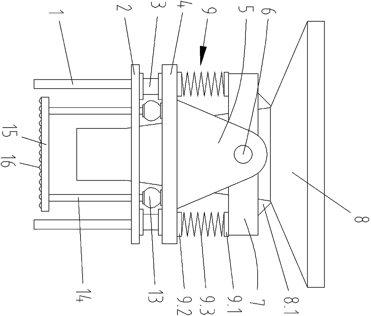
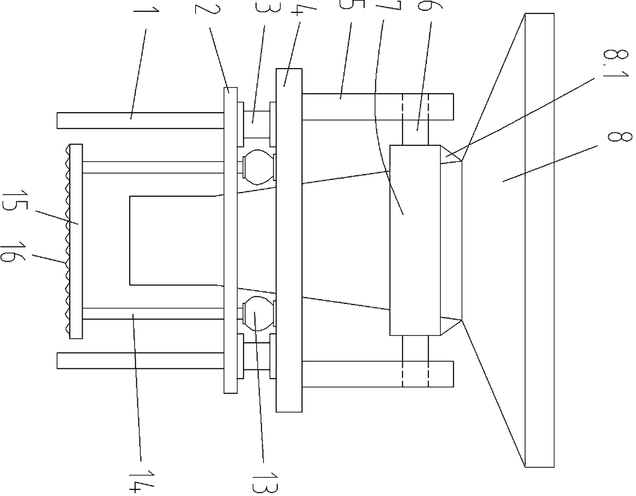
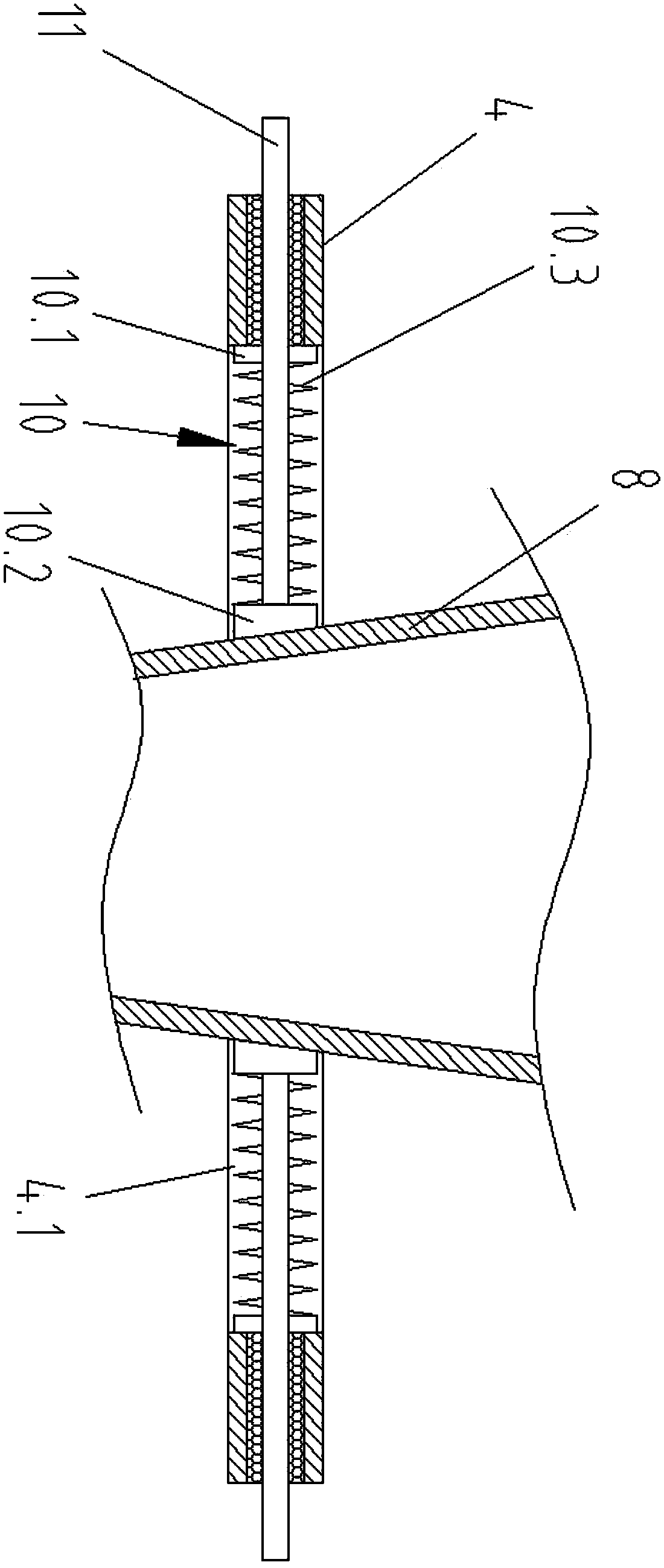
[0014] Such as figure 1 , figure 2 with image 3 As shown, the base installation structure of a convenient dismounting load cell provided by the present invention is characterized in that it includes a bracket, the bracket is a support plate 2 supported by four columns 1, the support plate 2 is a square structure, and the support plate 2 There is an opening in the center.

[0015] Load cells 3 are installed at the four corners above the support plate 2, and the upper sides of the four load cells 3 jointly support and connect the base plate 4. The base plate 4 is also a square structure, and the...


PUM


Abstract

The invention discloses a base mounting structure with weighing sensors being convenient to dismount. The base mounting structure comprises a support. The upper portion of the support is connected with a base plate through the set of weighing sensors in a supporting mode. Vertical plates are connected with the centers of the two sides of the upper portions of the base plate in a matched mode. A horizontal plate is connected between the two vertical plates through a rotary shaft in a rotating fit mode. A mounting hole is formed in the center of the upper side of the horizontal plate. A materialhopper is arranged at the mounting hole. A set of jacks are evenly arranged on the lower side of the base plate. A supporting column is fixedly connected with the lower end of a telescopic rod of each jack. The lower ends of the supporting columns are connected with an earth plate jointly and fixedly. The lower surface of the earth plate is a wavy rough surface. The base mounting structure has the advantages that the structure is simple, up-down and left-right instantaneous impact force on weighing sensing devices in the material pouring process can be effectively buffered, the service life of the weighing sensing devices is prolonged, when the weighing sensing devices need to be detected and calibrated, the earth plate is pushed by the jacks, and the weighing sensors can be dismounted conveniently.

Description

technical field [0001] The invention relates to the technical field of sensors, in particular to a base installation structure for convenient disassembly of a weighing sensor. Background technique [0002] In order to improve the proportioning accuracy and mixing efficiency of the mixture, a hopper with a weighing sensor device has appeared at present, which allows the user to further understand the weight of the material in the hopper by knowing the weight change of the current material in the hopper. However, at present, most of the load cells are fixed directly between the hopper and the bracket. The load cells are measuring tools, which need to be calibrated and tested regularly. They need to be removed during the test. The sensors of the existing structure It is inconvenient to disassemble, and the upper material hopper needs to be completely dismantled. Contents of the invention [0003] The purpose of the present invention is to solve the shortcomings in the prior ...

Claims


Application Information

Patent Timeline
Patent Type & Authority Applications(China)
IPC IPC(8): F16M11/16F16F15/04F16M11/26
CPCF16F15/04F16M11/16F16M11/26
Inventor 陈成
Owner BENGBU WANDA ELECTRONICS
Learn More