Eureka AIR delivers breakthrough ideas for toughest innovation challenges, trusted by R&D personnel around the world.

Stress deformation indoor model test device for shield tunnel structures and method for mounting stress deformation indoor model test device

A technology of force deformation and tunnel model, which is applied in the field of tunnel traffic simulation test, can solve the problems such as the inability to obtain the deformation and evolution law of shield tunnel structure, the degree of segment damage and the difficulty of acquisition, and achieve the simple structure of the device and the guarantee of consistency. Effect

Active Publication Date: 2018-10-26
CHINA UNIV OF GEOSCIENCES (WUHAN)
View PDF9 Cites 16 Cited by
  • Summary
  • Abstract
  • Description
  • Claims
  • Application Information

AI Technical Summary

Problems solved by technology

Due to the influence of factors such as water content in the rock and soil mass, it is difficult to collect data such as stress and strain during the model test; it is impossible to obtain the deformation evolution law of the shield tunnel structure and the damage degree of the segment under the surface load

Method used


Image

  • Stress deformation indoor model test device for shield tunnel structures and method for mounting stress deformation indoor model test device
  • Stress deformation indoor model test device for shield tunnel structures and method for mounting stress deformation indoor model test device
  • Stress deformation indoor model test device for shield tunnel structures and method for mounting stress deformation indoor model test device

Examples


Embodiment Construction

[0019] In order to make the purpose, technical solution and advantages of the present invention clearer, the embodiments of the present invention will be further described below in conjunction with the accompanying drawings.

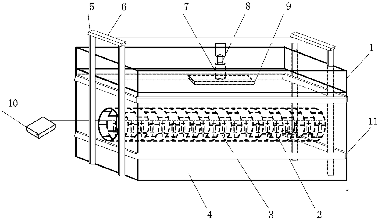
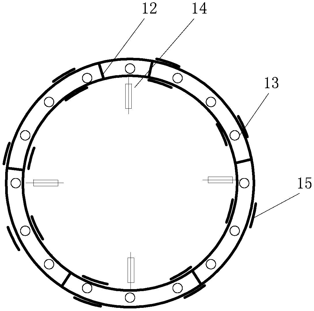
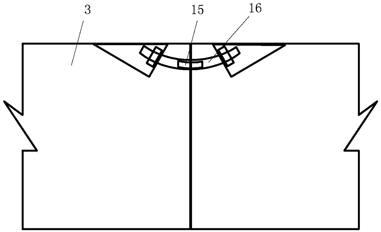
[0020] Please refer to figure 1 , the embodiment of the present invention provides a shield tunnel structure stress deformation indoor model test device, including a model tank 1, a tunnel model 2, a soil layer 4, and a pressure device; the tunnel model 2 is located in the model tank 1, and the Displacement gauge 14 and strain gauge 15 are arranged on the tunnel model 2, and described displacement gauge 14, strain gauge 15 are connected with data acquisition instrument 10, monitor and collect the stressed data change value of tunnel model 2 comprehensively in real time; Described soil layer 4 It is located above the tunnel model 2; the pressure device is located on the soil layer 4, and the pressure device exerts force on the tunnel model to simulate tem...


PUM


Abstract

An embodiment of the invention discloses a stress deformation indoor model test device for shield tunnel structures and a method for mounting the stress deformation indoor model test device. The stress deformation indoor model test device is characterized in that a tunnel model is positioned in a model groove, displacement meters and strain gauges are arranged on the tunnel model and are connectedwith a data acquisition instrument, and longitudinal and transverse deformation evolution conditions of the tunnel model after stress is applied to the tunnel model can be comprehensively monitored in real time; a soil layer is positioned around the tunnel model, and the properties of soil mass around real tunnels can be restored; a pressure device is positioned on the soil layer and is used forsimulating temporary pile-loading effects of earth surfaces. The stress deformation indoor model test device and the method have the advantages that the stress deformation indoor model test device isdesigned according to geometric similarity ratios and volume weight ratios of the actual tunnels, and accordingly the consistency of the stress deformation indoor model test device and prototype tunnels can be guaranteed; deformation evolution laws of the shield tunnel structures can be obtained by means of research on segment structure opening, slab staggering, bolt internal force, segment stressand convergence deformation conditions under simulated earth surface pile-loading conditions; damage degrees of segments under earth surface load can be evaluated on the basis of the deformation evolution laws, and reference can be provided to actual engineering.

Description

technical field [0001] The invention relates to the technical field of tunnel traffic simulation tests, in particular to an indoor model test device for stress deformation of a shield tunnel structure under the action of a temporary surface load. Background technique [0002] The model test research on the longitudinal and lateral deformation evolution mechanism of shield tunnel segments under temporary surface loading is usually carried out in the form of soil boxes, and the model is placed in the test soil medium. Due to the influence of factors such as water content in the rock and soil mass, it is difficult to collect data such as stress and strain during the model test; it is impossible to obtain the deformation evolution law of the shield tunnel structure and the damage degree of the segment under the surface load. Contents of the invention [0003] In view of this, an embodiment of the present invention provides a model test device that can be used indoors to simula...

Claims


Application Information

Patent Timeline
IPC IPC(8): G01B21/32
CPCG01B21/32
Inventor 梁荣柱吴文兵蒋学鹏张莉康成方宇翔霍利朋
Owner CHINA UNIV OF GEOSCIENCES (WUHAN)
Why Eureka
Eureka Blog
Learn More