Electrical adjusting light shutter device

A technology of electric adjustment and shutter, which is applied in optics, optical components, instruments, etc., can solve the problems of high optical system operation, difficulty in fast "opening of shutters", uncertain beam reflection path, etc.

Active Publication Date: 2018-10-26
INST OF APPLIED ELECTRONICS CHINA ACAD OF ENG PHYSICS
View PDF5 Cites 4 Cited by
  • Summary
  • Abstract
  • Description
  • Claims
  • Application Information

AI Technical Summary

Problems solved by technology

[0003] The purpose of the present invention is to provide a technical solution for electrically adjusting the shutter device in view of the deficiencies in the prior art. Due to defects such as inconvenient operation of the optical system, the light beam can be quickly "released" to realize its fast transmission function

Method used


Image

  • Electrical adjusting light shutter device

Examples


Embodiment

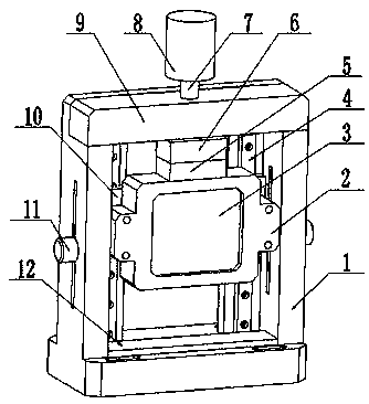
[0018] This device is in accordance with figure 1 The shown includes bracket, picture frame, reflector, guide rail, beam, iron block, electromagnet, lead screw and motor; the bracket is a rectangular hollow shape; the beam is fixed horizontally on the top of the bracket; the guide rail is vertically fixed in the bracket; the mirror frame is connected to the guide rail above; the motor is fixed above the beam; one end of the lead screw is connected to the motor, and the other end is connected to the electromagnet through the beam; the iron block is fixed on the top of the frame; the reflector is fixed in the frame; the electromagnet can absorb the iron block and Driven by the lead screw and the motor, the overall structure consisting of the iron block, frame and reflector moves freely up and down on the guide rail; The whole structure formed is in a state of free fall and falls on the bottom of the bracket along the guide rail. The guide rail and the picture frame are connecte...


PUM


Abstract

The invention provides an electrical adjusting light shutter device. According to the scheme, the electrical adjusting light shutter device comprises a support, a frame, a reflecting mirror, a guide rail, a crossbeam, an iron block, an electromagnet, a lead screw and a motor. The support is rectangular and hollow. The crossbeam is horizontally fixed on the top part of the support. The guide rail is vertically fixed in the support. The frame is connected on the guide rail. The motor is fixed on the crossbeam. One end of the lead screw is connected with the motor, and the other end penetrates through the crossbeam to be connected with the electromagnet. The iron block is fixed on the top part of the frame. The reflecting mirror is fixed in the frame. According to the scheme, the defects thatthe light beam reflecting path is uncertain and quick "shutter opening" is difficult to realize and operation of the high-power optical system is inconvenient can be overcome, and the light beams canbe quickly "released" to realize the quick transmission function.

Description

technical field [0001] The invention relates to the field of light beam adjustment in an optical system, in particular to an electric adjustment shutter device. Background technique [0002] When the beam is transmitted in the optical system, sometimes the laser is transmitted on the entire optical path. However, in the process of optical path debugging, testing or diagnosis, the beam transmission process only hopes to pass through part of the optical path. At the same time, some optical systems also hope that the beam output The performance indicators of the instantaneous beam, including the beam quality, power or energy, etc. reach the best state, which requires an optical gate device to be set at a certain position in the optical path to "cut off" the optical path. When the beam is adjusted to the best state or needs to be When the beam is output, the gate is quickly "opened" to transmit the beam in time. The traditional way of "cutting off" the optical path is basically...

Claims


Application Information

Patent Timeline
Patent Type & Authority Applications(China)
IPC IPC(8): G02B26/02
CPCG02B26/02
Inventor 李国会雒仲祥
Owner INST OF APPLIED ELECTRONICS CHINA ACAD OF ENG PHYSICS
Why Eureka
Try Eureka