
Pressure releasing passage of switch cabinet

A pressure relief channel and switchgear technology, applied in substation/switch layout details, electrical components, substation/distribution device shells, etc., can solve problems such as inconvenient handling and installation, high pressure release resistance, loss of lifting, etc. , to achieve the effect of convenient installation and operation, reducing the resistance of opening and improving the effect of pressure relief

Pending Publication Date: 2018-10-26
ZHENJIANG SCHNEIDER ELECTRIC
View PDF7 Cites 0 Cited by
  • Summary
  • Abstract
  • Description
  • Claims
  • Application Information

AI Technical Summary

Problems solved by technology

[0002] The switchgear products in the power transmission and distribution control equipment in the power industry need to have a pressure relief channel on the top to quickly discharge the high pressure in the cabinet caused by a sharp rise in temperature when a fault such as a short circuit or arc occurs during normal operation. Traditional switchgear products The pressure relief channel is generally provided with a pressure relief window on the top of the switch cabinet, and the top of the window is covered with a pressure relief plate, and the two sides of the pressure relief plate are fixedly connected to the top plate of the switch cabinet by screws. Quickly break through the plastic screws and open the pressure relief plate to open the pressure relief channel. Both sides of the pressure relief plate are fixedly connected at the same time. The high pressure release resistance in the cabinet is large. After the plastic screws on both sides of the pressure relief plate break through at the same time, the pressure relief plate is completely separated from the top plate of the switch cabinet, and it is easy to be lifted. Lost; and the upper surface of the pressure relief plate is flat, it is inconvenient to transport and install

Method used


Image

  • Pressure releasing passage of switch cabinet
  • Pressure releasing passage of switch cabinet
  • Pressure releasing passage of switch cabinet

Examples


Embodiment 2

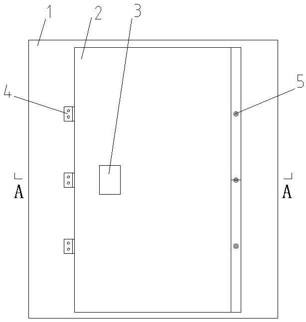
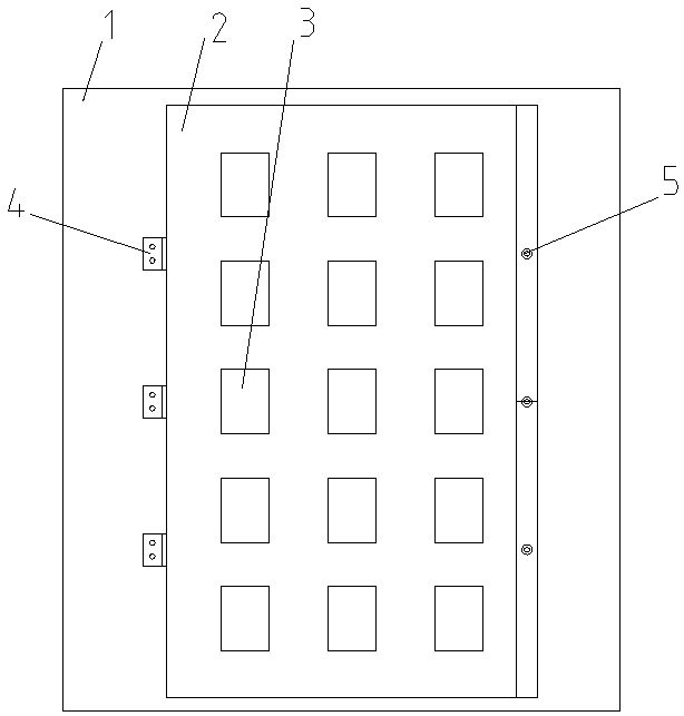
[0018] Embodiment 2 A plurality of grooves may be provided on the top plate of the pressure relief cover, and the plurality of grooves are evenly distributed in three rows and five columns, and the auxiliary pressure relief effect is good and the appearance is beautiful.

[0019] In the switchgear pressure relief channel of the present invention, both sides of the pressure relief cover are respectively connected to the top plate of the switchgear cabinet through plastic screws and hinges, which can reduce the resistance of the pressure relief cover to be opened, and the pressure relief cover will rotate along the hinge after being opened. , will not be lifted and lost, and the installation and connection are reliable. There is a downwardly concave groove on the top plate of the pressure cover. The through holes on the two side walls of the groove form auxiliary pressure relief holes to improve the pressure relief effect.


PUM


Abstract

The invention relates to a pressure releasing passage of a switch cabinet. A pressure releasing cover covers a pressure releasing window in a top plate of a cabinet body of the switch cabinet, one side of the pressure releasing cover is fixedly connected with the top plate of the cabinet body by a plastic screw, the other side of the pressure releasing cover is hinged with the top plate of the cabinet body via a hinge, a groove s formed in a top plate of the pressure releasing cover and is sunken, two side walls of the groove incline towards a downward and outward direction along a vertical central line of the groove so that the two side walls of the groove form a slanted inclined opening, through holes are formed in the two side walls of the groove, and the two sides of the pressure releasing cover are connected to the top plate of the cabinet body of the switch cabinet by the plastic screw and the hinge. The opening resistance of the pressure releasing cover can be reduced, the pressure releasing cover rotates and is turned over along the hinge after being opened and cannot be ripped off and lost, and the pressure releasing passage is reliable to install and connect; the groove is formed in the top plate of the pressure releasing cover and is sunken, the two side walls of the groove incline to form the slanted inclined opening, an edge of the groove is convenient to grasp, the carrying and installation operation is convenient, the through holes in the two side walls of the groove form auxiliary pressure releasing holes, and the pressure releasing effect is improved.

Description

technical field [0001] The invention relates to a pressure relief channel of a switch cabinet. Background technique [0002] The switchgear products in the power transmission and distribution control equipment in the power industry need to have a pressure relief channel on the top to quickly discharge the high pressure in the cabinet caused by a sharp rise in temperature when a fault such as a short circuit or arc occurs during normal operation. Traditional switchgear products The pressure relief channel is generally provided with a pressure relief window on the top of the switch cabinet, and the top of the window is covered with a pressure relief plate, and the two sides of the pressure relief plate are fixedly connected to the top plate of the switch cabinet by screws. Quickly break through the plastic screws and open the pressure relief plate to open the pressure relief channel. Both sides of the pressure relief plate are fixedly connected at the same time. The high press...

Claims


Application Information

Patent Timeline
Patent Type & Authority Applications(China)
IPC IPC(8): H02B1/30
CPCH02B1/306
Inventor 陈跃宏
Owner ZHENJIANG SCHNEIDER ELECTRIC
Learn More