Sweeper

A sweeping machine and body technology, applied in the field of sweeping machines, can solve the problems of high production cost, complicated structure, and inability to accurately control the water output of the water tank, and achieve the effect of low production cost, accurate water output, and elimination of self-priming water

Pending Publication Date: 2018-11-02
张奥雨
View PDF0 Cites 16 Cited by
  • Summary
  • Abstract
  • Description
  • Claims
  • Application Information

AI Technical Summary

Problems solved by technology

[0002] There are two control methods for the water tank of the sweeping machine in the prior art in mopping the floor: one is the self-flowing water of the water tank, which cannot accurately control the water output of the water tank; the other is to use a water pump to control the water flow, which has a complex structure and high production costs.

Method used


Image

  • Sweeper
  • Sweeper
  • Sweeper

Examples


Embodiment

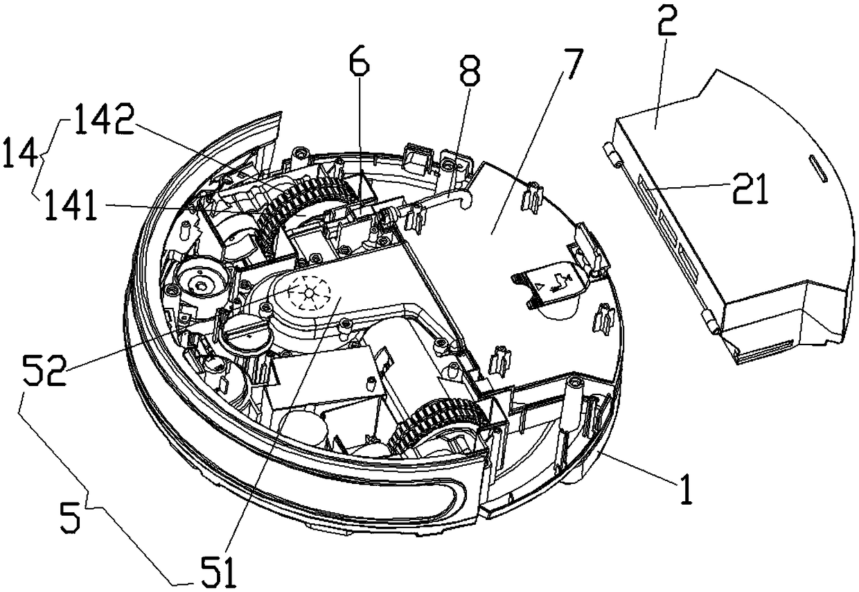
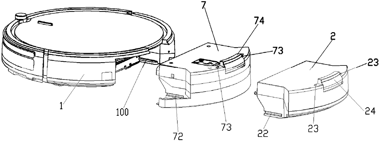
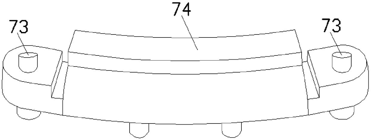
[0034] Such as Figure 1 to Figure 8 As shown, this embodiment provides a sweeping machine body, including a sweeping machine body 1, the bottom of the sweeping machine body 1 is provided with a universal wheel mechanism 13, a driving wheel set and a dust suction port 3, and the sweeping machine body 1 is also provided with an air pump 6 and a power supply for supplying power to the air pump 6. A water tank 7 can also be detachably installed in the sweeper body 1. The air pump 6 is connected to a conduit 8. An air pipe 71 is provided in the water tank 7. , the upper end of the air pipe 71 communicates with the conduit 8, the lower end of the air pipe 71 is close to the bottom wall of the water tank 7 and the lower end of the air pipe 71 has an air outlet, and the bottom wall of the water tank 7 is provided with a capillary outlet hole 9, so that the water in the water tank 7 has a first state that can flow out when the air pump 6 pressurizes the water tank 7, and when the air ...


PUM


Abstract

The invention belongs to the technical field of cleaning equipment, and particularly relates to a sweeper which comprises a sweeper body. A universal wheel mechanism, a driving wheel set and a suctioninlet are arranged at the bottom of the sweeper body, an air pump and a power supply for supplying power for the air pump are further arranged in the sweeper body, a water tank is detachably arrangedin the sweeper body, the air pump is connected with a guide pipe, a capillary water outlet hole is formed in the bottom wall of the water tank, a mop is further arranged on the outer wall of the bottom wall of the water tank, an interlayer is further arranged between the bottom wall of the water tank and the mop, and a water passing hole corresponding to the capillary water outlet hole is formedin the interlayer. The air pump of the sweeper intermittently supplies air for the water tank and pumps out water in the water tank through the capillary water outlet hole to accurately control the water outlet quantity of the water tank, and the sweeper has the advantages of simple and reasonable structure, low production cost, accurate water outlet quantity and the like.

Description

technical field [0001] The invention belongs to the technical field of cleaning equipment, and in particular relates to a sweeping machine. Background technique [0002] There are two control methods for the water tank of the sweeping machine in the prior art in terms of mopping the floor: one is that the water tank flows out automatically, and the water output of the water tank cannot be accurately controlled; the other is to use a water pump to control the water flow, which has a complex structure and high production costs. Contents of the invention [0003] In order to solve the above-mentioned problems existing in the prior art, the present invention provides a floor sweeper, aiming at the fact that the floor sweeper in the prior art cannot accurately control the water output of the water tank or uses a water pump to control the water output of the water tank when the structure is complicated and the production cost is high. The research and development has the advanta...

Claims


Application Information

Patent Timeline
Patent Type & Authority Applications(China)
IPC IPC(8): A47L11/28A47L11/40
CPCA47L11/28A47L11/40A47L11/4013A47L11/4083A47L11/4088
Inventor 张奥雨
Owner 张奥雨
Why Eureka
Try Eureka