Arrangement for working a tube end

A technology of pipe ends and tools, which is applied in the field of devices for processing pipe ends, and can solve problems such as low power, cylinder damage, and complicated control of hydraulic cylinders

Pending Publication Date: 2018-11-02
DANFOSS POWER SOLUTIONS II TECH AS
View PDF9 Cites 0 Cited by
  • Summary
  • Abstract
  • Description
  • Claims
  • Application Information

AI Technical Summary

Problems solved by technology

The disadvantage is that a hydraulic cylinder with less power must be used
If two parallel hydraulic cylinders are used to make up for power loss, the contro...

Method used


Image

  • Arrangement for working a tube end
  • Arrangement for working a tube end
  • Arrangement for working a tube end

Examples


Embodiment Construction

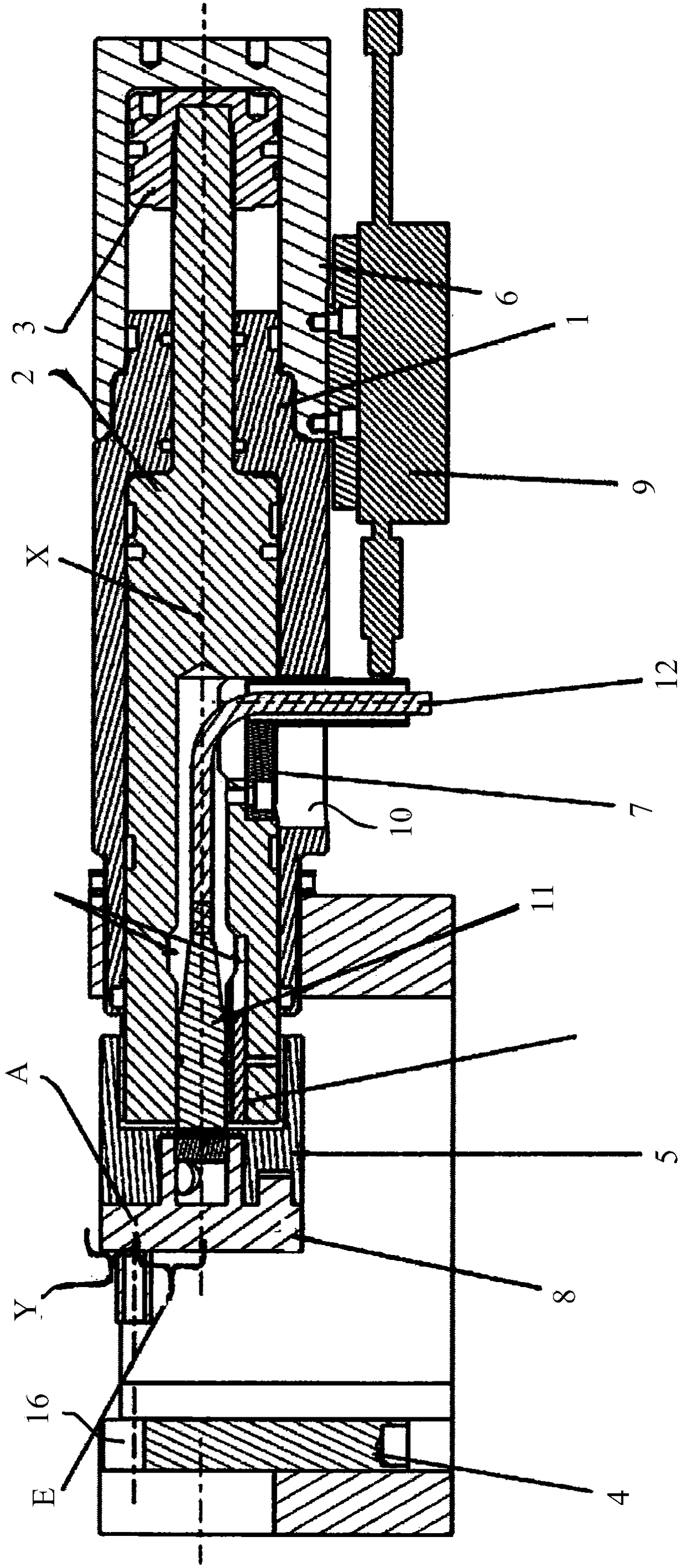
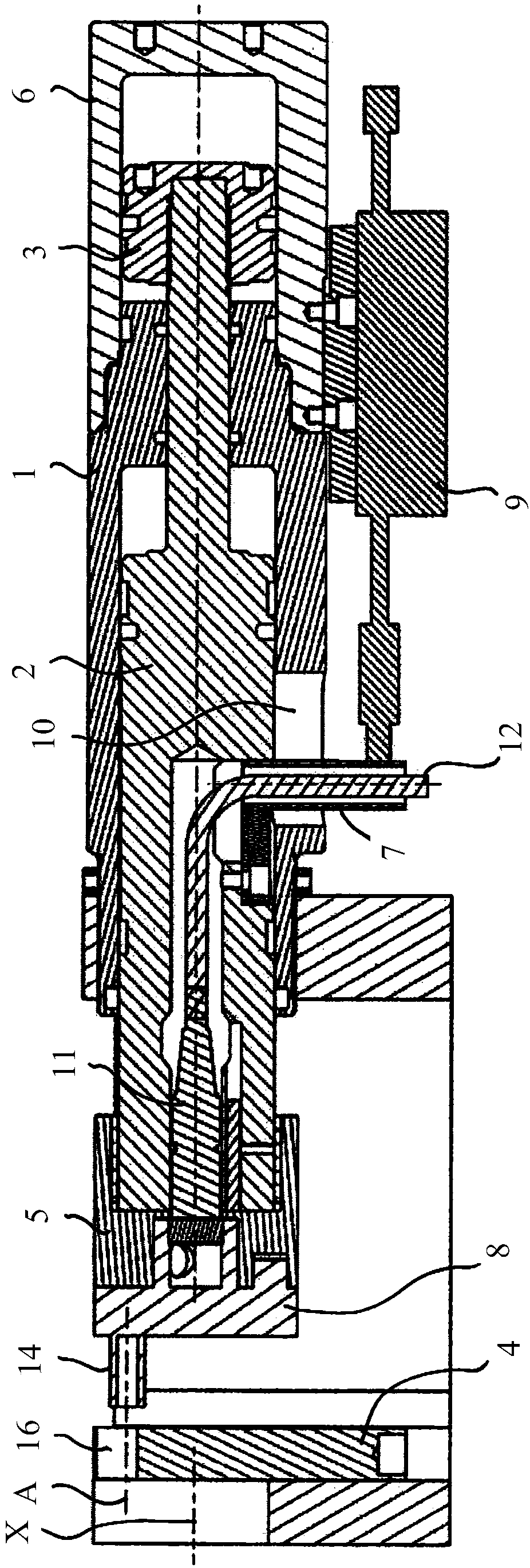
[0018] exist figure 1 with figure 2 In each case is shown a sectional view along the longitudinal axis X of an embodiment of the device for processing pipe ends according to the invention. figure 1 The first machining position is shown, where the pistons 2, 3 are retracted, figure 2 A second machining position is shown, where the pistons 2,3 extend from the operating cylinders 1,6.

[0019] These drawings will be described together.

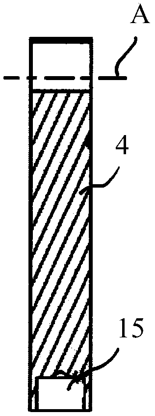
[0020] The pistons 2, 3 are displaceable along the longitudinal axis X, and the tube mount 4 is adapted to fix a tube end (not shown) in such a way that it is axially aligned parallel to the longitudinal axis. A tool holder 5 is provided at the end of the pistons 2 , 3 facing the pipe mounting 4 .

[0021] The operating cylinders 1, 6 are arranged in tandem, wherein the first stage cylinder 1 and the second stage cylinder 6 are arranged staggered along the longitudinal axis X, and the pistons 2, 3 comprise a first piston section connected t...


PUM


Abstract

Arrangement for working a tube end comprises an cylinder (1,6, figure 2) with a piston 2,3 displaceable along an longitudinal axis X, and a tube mounting 4. A tool holder 5 at an end of the piston faces the mounting. The cylinder is a tandem comprising at least two cylinder stages located along the axis X each having corresponding piston segments connected together. A tool may be attached to the tool holder with an operating axis A radially offset to have an eccentricity E relative to the axis X. The arrangement allows for accommodation of a curved tube the legs of which have a minimum spacingY. The mounting 4 or tool (8, figure 4a) may have a data carrier containing data relating to the respective part which can be read by a sensor (11) inside the piston. Protection 7 may prevent the piston from twisting relative to the operating cylinder, and may comprise a radial protrusion from first segment 2 extending through a wall of the first cylinder (1). Signal line 12, and optional power line, may run from sensor (11) through the anti-twist protection 7. Sensor 9 may detect the longitudinal position of anti-twist projection 7.

Description

technical field [0001] The invention relates to a device for machining pipe ends comprising an operating cylinder with a piston displaceable along a longitudinal axis and a pipe mount, wherein a tool support is arranged at the end of the piston facing the pipe mount . Background technique [0002] In the field of machining at or near the end of pipe, such as in residential plumbing applications, it is common and convenient to use clamping mechanisms that hold the pipe to be A machine that processes a tool on a plunger in front of the end of a pipe and the tool is forced towards the end of the pipe, for example by rotating a threaded member in a corresponding threaded support bracket or by a hydraulic cylinder, the end being thus machined, i.e. Formed in some way, for example by expanding the tube end or by expanding the tube. For example, a further typical application is the fitting of cutting rings to pipe ends for subsequent weld-free oval pipe joints. [0003] In DE 10...

Claims


Application Information

Patent Timeline
IPC IPC(8): B25B11/00B25B11/02B21D41/02B21D41/00
CPCB21D41/00B21D41/02B25B11/00B25B11/02B21D19/06B21D19/12B21D19/16B21D41/023B21D41/025B21D39/203B23Q3/082B23Q2703/02B23Q2703/12B25B5/087
Inventor M·茂巴赫
Owner DANFOSS POWER SOLUTIONS II TECH AS
Why Eureka
Try Eureka