
Robot joint module

A technology of robot joints and modules, which is applied in the field of robots, can solve problems such as safety hazards and clutter, and achieve high safety effects

Pending Publication Date: 2018-11-02
SHENZHEN HYPERMAGNETIC ROBOT TECH CO LTD
View PDF8 Cites 2 Cited by
  • Summary
  • Abstract
  • Description
  • Claims
  • Application Information

AI Technical Summary

Problems solved by technology

[0003] In order to control the robot, wiring is required. Existing robots generally use external wiring, which is messy and poses a safety hazard.

Method used


Image

  • Robot joint module
  • Robot joint module
  • Robot joint module

Examples


Embodiment Construction

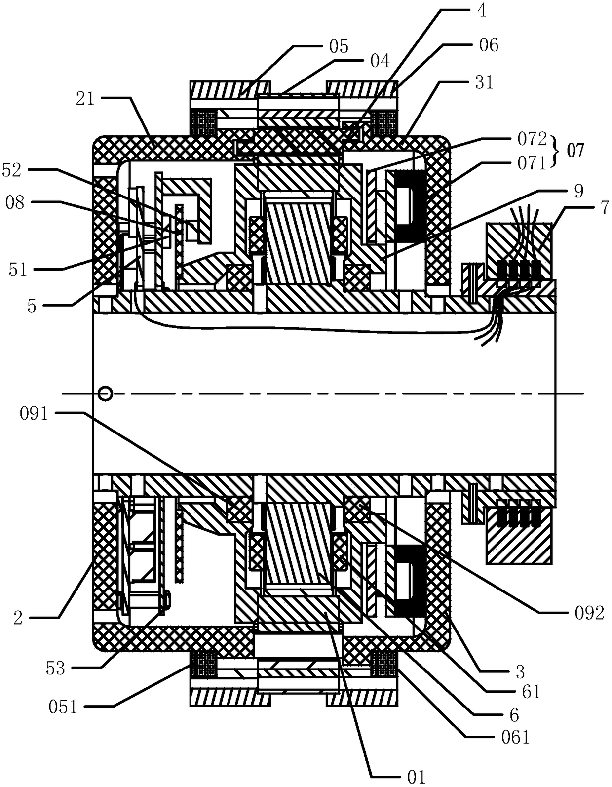
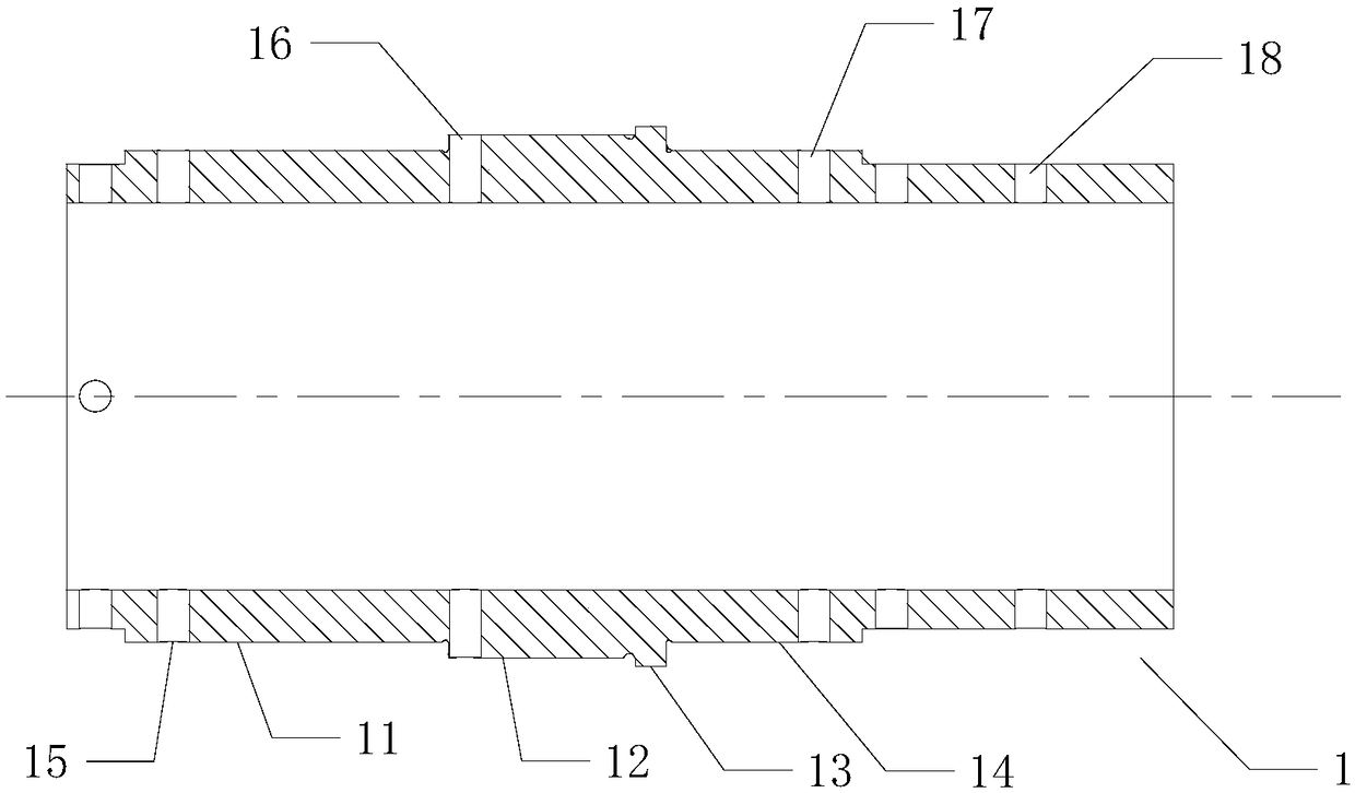
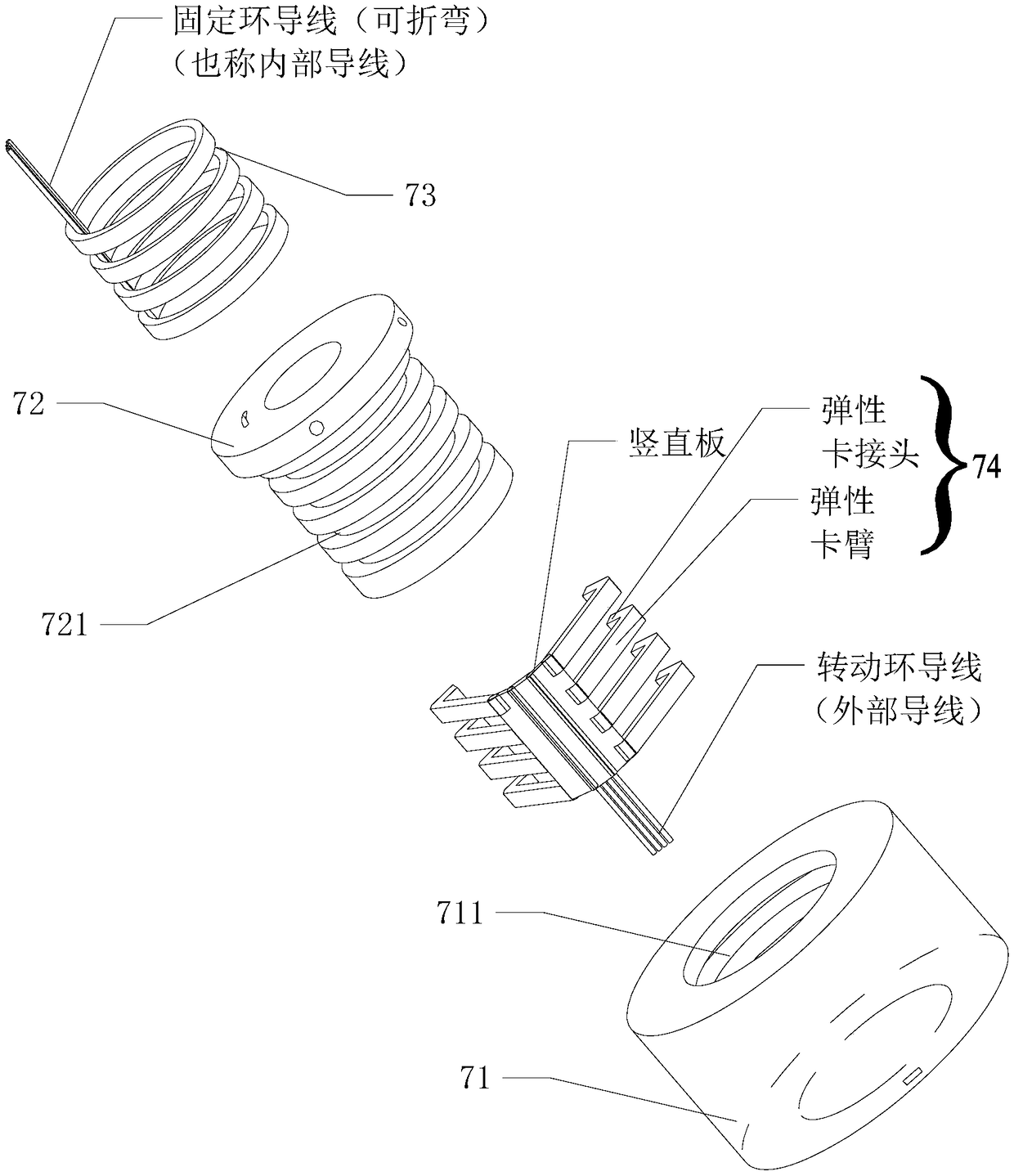
[0052] Attached below Figure 1~3 A robot joint module of the present invention will be further described.

[0053] A robot joint module, comprising a straight shaft 1, and further comprising: a front magnetic adjustment support 2, a rear magnetic adjustment support 3, a magnetic adjustment armature 4, a circuit board 5, a stator core 6 and a slip ring 7;

[0054] The front magnet adjustment bracket 2 is sleeved on the outer circumference of the front end of the direct shaft 1, and the rear magnet adjustment bracket 3 is sleeved on the outer circumference of the rear section of the direct shaft 1; the rear magnetic adjustment bracket 3 protrudes forward from the first ring-shaped surrounding part 31 , the front magnetic adjustment bracket 2 protrudes backward from the second annular wrapping part 21; the two ends of the magnetic adjustment armature 4 are respectively plugged into the front end surface of the first annular wrapping part 31 and the rear end surface of the second...


PUM


Abstract

The invention relates to a robot joint module. A front magnetic adjustment bracket is sleeved with the outer circumference of the front end of a straight shaft, and a rear magnetic adjustment bracketis sleeved with the outer circumference of the rear end of the straight shaft; the rear magnetic adjustment bracket protrudes forwards from a first annular wrapping part, and the front magnetic adjustment bracket is protrudes backwards from a second annular wrapping part; the two ends of a magnetically adjustable armature are respectively connected with the front end surface of the first annular wrapping part and the rear end surface of the second annular wrapping part in an inserting way; the straight shaft, the front magnetic adjustment bracket, the rear magnetic adjustment bracket and the outer side of the magnetically adjustable armature define a semi-closed space; the straight shaft in the semi-closed space is sleeved with a circuit board and a stator core; the stator core is wound with a stator coil; a collector ring is sleeved with the straight shaft at the rear side of the rear magnetic adjustment bracket; the straight shaft is hollow, and the straight shaft is provided with aplurality of wire through holes; the wires of the circuit board pass through the wire through holes, and the inner hollow part of the straight shaft is separately connected with the collector ring andthe stator coil; therefore, internal wiring is realized, disorder is not caused, and the safety is high.

Description

technical field [0001] The invention relates to the technical field of robots, in particular to a robot joint module. Background technique [0002] With the increase of labor costs and the development of technology, a large number of robots have been applied in many factories and life service fields. [0003] In order to control the robot, wiring needs to be carried out. Existing robots generally use external wiring, which is messy and poses a safety hazard. Contents of the invention [0004] The technical problem to be solved by the present invention is: to propose a robot joint module, the interior of the rotating shaft is hollow, and the interior can be routed without causing mess and high safety. [0005] A robot joint module, including a straight shaft, a front magnetic adjustment bracket, a rear magnetic adjustment bracket, a magnetic adjustment armature, a circuit board, a stator core and a collector ring; [0006] The front magnetic adjustment bracket is sleeved ...

Claims


Application Information

Patent Timeline
Patent Type & Authority Applications(China)
IPC IPC(8): B25J17/02H02K13/00
CPCH02K1/2786H02K1/28H02K5/165H02K7/09H02K11/0094H02K11/20H02K11/21H02K11/33H02K13/003H02K16/02F16C32/0444F16C32/0474B25J17/0258H02K2213/03F16C2380/26
Inventor 李渊张天洪黄勇军刘伟平
Owner SHENZHEN HYPERMAGNETIC ROBOT TECH CO LTD
Learn More